Bolt Pattern Force Distribution Validation
This section details the validation for the Bolt Pattern Force Distribution calculator. Several examples are worked through to determine expected axial and shear forces on each bolt. These expected results are then compared to the actual output of the calculator.
Case 1: 4-Bolt Rectangular Pattern
Inputs
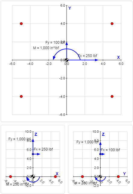
In this validation case, a 4-bolt rectangular pattern will be analyzed. The bolts have the following locations:
| Bolt # | X | Y |
|---|---|---|
| 1 | -5 in | 4 in |
| 2 | -5 in | -4 in |
| 3 | 5 in | 4 in |
| 4 | 5 in | -4 in |
Each bolt in the pattern has a 1/4-20 thread, so the tensile stress area of each bolt is:
$$ A_t = 0.03182 \text{ in}^2 $$A force of [Fx = 250 lbf, Fy = 100 lbf, Fz = 1000 lbf] is applied at a location 5 inches above the origin:
| Force Value | Location | |||||
|---|---|---|---|---|---|---|
| Fx | Fy | Fz | Lx | Ly | Lz | |
| 250 lbf | 100 lbf | 1,000 lbf | 0 in | 0 in | 5 in | |
A moment of [Mx = -250 in*lbf, My = 250 in*lbf, Mz = 1,000 in*lbf] is applied to the pattern:
| Moment Value | ||
|---|---|---|
| Mx | My | Mz |
| -250 in*lbf | 250 in*lbf | 1,000 in*lbf |
Manual Calculations
Pattern Properties
The combined area of all bolts in the pattern is:
$$ A_{cmb} = \sum_i A_i = 4 \cdot (0.03182 \text{ in}^2) = 0.1273 \text{ in}^2 $$The centroid location in the x-direction is:
$$ x_c = { \sum_i x_i A_i \over \sum_i A_i } = { A_t \cdot ( x_1 + x_2 + x_3 + x_4 ) \over A_{cmb} } = { (0.03182 \text{ in}^2) \cdot ( -5 \text{ in} - 5 \text{ in} + 5 \text{ in} + 5 \text{ in} ) \over 0.1273 \text{ in}^2 } = 0 \text{ in} $$The centroid location in the y-direction is:
$$ y_c = { \sum_i y_i A_i \over \sum_i A_i } = { A_t \cdot ( y_1 + y_2 + y_3 + y_4 ) \over A_{cmb} } = { (0.03182 \text{ in}^2) \cdot ( 4 \text{ in} - 4 \text{ in} + 4 \text{ in} - 4 \text{ in} ) \over 0.1273 \text{ in}^2 } = 0 \text{ in} $$Because the centroid is located at the origin, the distance of each bolt from the centroid is simply the location of the bolt:
| Bolt # | rc.x | rc.y |
|---|---|---|
| 1 | -5 in | 4 in |
| 2 | -5 in | -4 in |
| 3 | 5 in | 4 in |
| 4 | 5 in | -4 in |
The centroidal moment of inertia of the bolt pattern about the x-axis is:
$$ I_{c.x} = \sum_i r_{c.y,i}^2 A_i = A_t \cdot ( r_{c.y,1}^2 + r_{c.y,2}^2 + r_{c.y,3}^2 + r_{c.y,4}^2 ) = (0.03182 \text{ in}^2) \cdot [ (4 \text{ in})^2 + (-4 \text{ in})^2 + (4 \text{ in})^2 + (-4 \text{ in})^2 ] = 2.037 \text{ in}^4 $$The centroidal moment of inertia of the bolt pattern about the y-axis is:
$$ I_{c.y} = \sum_i r_{c.x,i}^2 A_i = A_t \cdot ( r_{c.x,1}^2 + r_{c.x,2}^2 + r_{c.x,3}^2 + r_{c.x,4}^2 ) = (0.03182 \text{ in}^2) \cdot [ (-5 \text{ in})^2 + (-5 \text{ in})^2 + (5 \text{ in})^2 + (5 \text{ in})^2 ] = 3.182 \text{ in}^4 $$The centroidal polar moment of inertia of the bolt pattern is:
$$ I_{c.p} = I_{c.x} + I_{c.y} = 2.037 \text{ in}^4 + 3.182 \text{ in}^4 = 5.219 \text{ in}^4 $$The following table summarizes the pattern properties calculated above:
| Property | Value | Description |
|---|---|---|
| Acmb | 0.1273 in2 | combined area of all bolts in the pattern |
| xc | 0 in | X-coordinate of the pattern centroid |
| yc | 0 in | Y-coordinate of the pattern centroid |
| Ic.x | 2.037 in4 | centroidal moment of inertia about X-axis |
| Ic.y | 3.182 in4 | centroidal moment of inertia about Y-axis |
| Ic.p | 5.219 in4 | centroidal polar moment of inertia |
Forces & Moments at Centroid
There is only one applied force, \(F\), applied at location \(L\):
| $$ F = \left[ \begin{array}{c} 250 \\ 100 \\ 1000 \end{array} \right] \text{ lbf} $$ | $$ L = \left[ \begin{array}{c} 0 \\ 0 \\ 5 \end{array} \right] \text{ in} $$ |
Because the centroid is located at the origin, vector \(R\) from the pattern centroid to the applied force location is equal to \(L\):
$$ R = L = \left[ \begin{array}{c} 0 \\ 0 \\ 5 \end{array} \right] \text{ in} $$There is only one applied moment, \(M\):
$$ M = \left[ \begin{array}{c} -250 \\ 250 \\ 1000 \end{array} \right] \text{ in*lbf} $$The applied forces and moments are translated to the centroid of the pattern. The forces at the centroid are simply the sum of the applied forces:
$$ F_c = \sum_i F_i = \left[ \begin{array}{c} 250 \\ 100 \\ 1000 \end{array} \right] \text{ lbf} $$The moments at the centroid are calculated as:
$$ M_c = \sum_i M_i + \sum_i \left( R_{c,i} \times F_i \right) = \left[ \begin{array}{c} -250 \text{ in*lbf} \\ 250 \text{ in*lbf} \\ 1000 \text{ in*lbf} \end{array} \right] + \left[ \begin{array}{c} 0 \text{ in} \\ 0 \text{ in} \\ 5 \text{ in} \end{array} \right] \times \left[ \begin{array}{c} 250 \text{ lbf} \\ 100 \text{ lbf} \\ 1000 \text{ lbf} \end{array} \right] = \left[ \begin{array}{c} -750 \\ 1500 \\ 1000 \end{array} \right] \text{ in*lbf} $$Now that the forces and moments at the pattern centroid have been calculated, they can be used to calculate the forces acting on individual bolts. To summarize, the forces and moments at the centroid are:
| $$ F_c = \left[ \begin{array}{c} 250 \\ 100 \\ 1000 \end{array} \right] \text{ lbf} $$ | $$ M_c = \left[ \begin{array}{c} -750 \\ 1500 \\ 1000 \end{array} \right] \text{ in*lbf} $$ |
Individual Bolt Forces
Axial Forces on Bolts
The direct force in the Z-direction, \(F_{c.z}\), is divided between the bolts according to the bolt stiffnesses. Because the bolts are all assumed to have the same material and length, the stiffness is dependent only on area. The axial force on a bolt due to the direct force in Z is calculated as:
$$ P_{z.FZ} = { F_{c.z} A \over \sum_i A_i } $$where \(A\) is the area of the bolt in question. Because the bolts all have the same area in this case, \(P_{z.FZ}\) is the same for each bolt:
$$ P_{z.FZ} = { F_{c.z} A \over \sum_i A_i } = { (1000 \text{ lbf}) (0.03182 \text{ in}^2) \over 0.1273 \text{ in}^2 } = 250 \text{ lbf} $$The axial force on a bolt due to moment about X-axis is calculated as:
$$ P_{z.MX} = { M_{c.x} r_{c.y} \over I_{c.x} } \cdot A $$where \(M_{c.x}\) is the centroidal moment about the X-axis, \(r_{c.y}\) is the bolt distance from the centroid in the Y-direction, and \(I_{c.x}\) is the pattern moment of inertia about the X-axis.
In this case, every bolt lies at the same distance from the X-axis, with the only exception being the direction (either above or below the axis). The forces on the bolts below the X-axis are:
$$ P_{z.MX} = { M_{c.x} r_{c.y} \over I_{c.x} } \cdot A = { (-750 \text{ in*lbf}) (-4 \text{ in}) \over 2.037 \text{ in}^4 } \cdot (0.03182 \text{ in}^2) = 46.875 \text{ lbf} $$The forces on the bolts above the X-axis are the negative of the forces on the bolts below.
The axial force on a bolt due to moment about Y-axis is calculated as:
$$ P_{z.MY} = { M_{c.y} r_{c.x} \over I_{c.y} } \cdot A $$where \(M_{c.y}\) is the centroidal moment about the Y-axis, \(r_{c.x}\) is the bolt distance from the centroid in the X-direction, and \(I_{c.y}\) is the pattern moment of inertia about the Y-axis.
In this case, every bolt lies at the same distance from the Y-axis, with the only exception being the direction (either to the left or right of the axis). The forces on the bolts to the left the Y-axis are:
$$ P_{z.MY} = -{ M_{c.y} r_{c.x} \over I_{c.y} } \cdot A = -{ (1500 \text{ in*lbf}) (-5 \text{ in}) \over 3.182 \text{ in}^4 } \cdot (0.03182 \text{ in}^2) = 75.00 \text{ lbf} $$The forces on the bolts to the right the Y-axis are the negative of the forces on the bolts to the left.
The total axial force on a bolt is the sum of the axial force components calculated above:
$$ P_{axial} = P_{z.FZ} + P_{z.MX} + P_{z.MY} $$The maximum axial force will occur on the bolt for which all of the axial force components are positive.
The following table summarizes the axial forces on the bolts:
| Bolt # | rc.x | rc.y | Paxial | Pz.FZ | Pz.MX | Pz.MY | |
|---|---|---|---|---|---|---|---|
| 1 | -5 in | 4 in | 278.125 lbf | 250.00 lbf | -46.875 lbf | 75.00 lbf | |
| 2 | -5 in | -4 in | 371.875 lbf | 250.00 lbf | 46.875 lbf | 75.00 lbf | |
| 3 | 5 in | 4 in | 128.125 lbf | 250.00 lbf | -46.875 lbf | -75.00 lbf | |
| 4 | 5 in | -4 in | 221.875 lbf | 250.00 lbf | 46.875 lbf | -75.00 lbf |
Shear Forces on Bolts
The calculation of the shear forces is assisted by drawing a free body diagram showing the reaction forces on each bolt in the pattern:
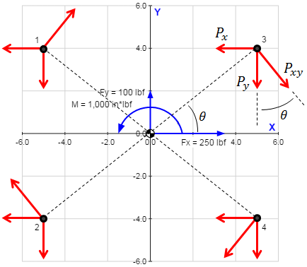
The table below summarizes the dimensions of interest for the bolts in the pattern:
| Bolt # | rc.x | rc.y | rc.xy | θ |
|---|---|---|---|---|
| 1 | -5 in | 4 in | 6.403 in | 141.3 deg |
| 2 | -5 in | -4 in | 6.403 in | -141.3 deg |
| 3 | 5 in | 4 in | 6.403 in | 38.66 deg |
| 4 | 5 in | -4 in | 6.403 in | -38.66 deg |
The value \(r_{c.xy}\) in the table above is the shortest distance between the bolt and the centroid and is calculated as \(r_{c.xy} = \sqrt{ r_{c.x}^2 + r_{c.y}^2 } \). The value \(\theta\) is the angle between the bolt location and the positive X-axis and is calculated as \( \theta = \tan^{-1}({ r_{c.y} / r_{c.x} }) \).
The direct forces in the X- and Y- directions, \(F_{c.x}\) and \(F_{c.y}\), respectively, are divided between the bolts according to the bolt stiffnesses. Because the bolts are all assumed to have the same material and length, the stiffness is dependent only on area. The shear forces on a bolt due to the direct forces in X- and Y- are calculated as:
| $$ P_{x.FX} = -{ F_{c.x} A \over \sum_i A_i } $$ | $$ P_{y.FY} = -{ F_{c.y} A \over \sum_i A_i } $$ |
where \(A\) is the area of the bolt in question. Because the bolts all have the same area in this case, \(P_{x.FX}\) and \(P_{y.FY}\) are the same for each bolt:
$$ P_{x.FX} = -{ F_{c.x} A \over \sum_i A_i } = -{ (250 \text{ lbf}) (0.03182 \text{ in}^2) \over 0.1273 \text{ in}^2 } = -62.50 \text{ lbf} $$ $$ P_{y.FY} = -{ F_{c.y} A \over \sum_i A_i } = -{ (100 \text{ lbf}) (0.03182 \text{ in}^2) \over 0.1273 \text{ in}^2 } = -25.00 \text{ lbf} $$The shear force on a bolt due to moment about Z-axis is calculated as:
$$ P_{xy.MZ} = { M_{c.z} r_{c.xy} \over I_{c.p} } \cdot A $$where \(M_{c.z}\) is the centroidal moment about the Z-axis, \(r_{c.xy}\) is the shortest distance between the bolt and the centroid, and \(I_{c.p}\) is the pattern's polar moment of inertia.
Because every bolt in the pattern is located at the same distance from the centroid, the magnitude of \(P_{xy.MZ}\) is the same for every bolt:
$$ P_{xy.MZ} = { M_{c.z} r_{c.xy} \over I_{c.p} } \cdot A = { (1000 \text{ in*lbf}) (6.403 \text{ in}) \over (5.219 \text{ in}^4) } \cdot (0.03182 \text{ in}^2) = 39.04 \text{ lbf} $$The shear force calculated above is then resolved into X- and Y- components based on the value of \(\theta\) (see the table above):
$$ P_{x.MZ} = P_{xy.MZ} \cdot \sin{ \theta } = (39.04 \text{ lbf}) \cdot \sin({ 39 ^{\circ} }) = 24.390 \text{ lbf} $$ $$ P_{y.MZ} = P_{xy.MZ} \cdot \cos{ \theta } = (39.04 \text{ lbf}) \cdot \cos({ 39 ^{\circ} }) = 30.488 \text{ lbf} $$The total shear force on a bolt is calculated as the vector sum of the X- components plus the Y- components:
$$ P_{shear} = \sqrt{ (P_{x.FX} + P_{x.MZ})^2 + (P_{y.FY} + P_{y.MZ})^2 } $$The following table summarizes the shear forces on the bolts:
| Bolt # | rc.x | rc.y | Pshear | Px.FX | Py.FY | Px.MZ | Py.MZ | |
|---|---|---|---|---|---|---|---|---|
| 1 | -5 in | 4 in | 38.503 lbf | -62.50 lbf | -25.00 lbf | 24.390 lbf | 30.488 lbf | |
| 2 | -5 in | -4 in | 87.063 lbf | -62.50 lbf | -25.00 lbf | -24.390 lbf | 30.488 lbf | |
| 3 | 5 in | 4 in | 67.315 lbf | -62.50 lbf | -25.00 lbf | 24.390 lbf | -30.488 lbf | |
| 4 | 5 in | -4 in | 103.096 lbf | -62.50 lbf | -25.00 lbf | -24.390 lbf | -30.488 lbf |
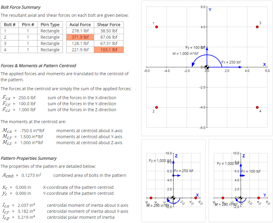
Bolt Force Summary
The following table summarizes the axial and shear forces on each bolt, as calculated above:
| Bolt # | Axial Force | Shear Force |
|---|---|---|
| 1 | 278.125 lbf | 38.503 lbf |
| 2 | 371.875 lbf | 87.063 lbf |
| 3 | 128.125 lbf | 67.315 lbf |
| 4 | 221.875 lbf | 103.096 lbf |
Comparison With Calculator
The results summary page from the calculator is shown below. It can be seen that the results from the calculator match the results calculated above.