


Bolt Pattern Force Distribution
A bolt pattern is arrangement of bolted joints, typically four or more, that connect two or more components together. When designing a bolt pattern, it is important to understand the loads that the pattern will need to resist in operation as well as the way in which those applied loads will distribute among the individual bolted joints in the pattern. Once the axial and shear loads have been calculated for the individual bolted joints in the pattern, the individual joints can be analyzed as discussed in our Bolted Joint Analysis reference.
The following sections detail the methodology to resolve forces and moments applied to a bolt pattern into axial and shear loads acting on the individual bolted joints in the pattern.
Contents
Overview and Discussion
The distribution of forces and moments over a bolt pattern is similar to the analysis of a beam or a shaft. Applied loads are translated to the centroid of the pattern (analogous to the neutral axis of a beam or shaft). The forces and moments at the centroid are then resolved into axial and shear forces acting at the individual bolted joints. Axial forces are distributed over a bolt pattern based on pattern's area, A, and moments of inertia, Ic.x and Ic.y. Likewise, shear forces are distributed based on the pattern's area, A, and polar moment of inertia, Ic.p.
Note that we maintain the distinction that the forces are distributed to individual bolted joints rather than individual bolts. The reason for this is that not all of the load applied to a bolted joint is actually seen by the bolt, as discussed here.
Two common loading conditions are discussed in the next two sections, followed by a discussion of the generalized approach for distributing applied loads over a bolt pattern.
In-Plane Eccentric Shear Load
The figure below shows a pattern with an eccentric shear load that is applied in the plane of the pattern. The load is eccentric because it does not act through the centroid of the pattern. Therefore, it induces a torsional moment about the Z-axis (perpendicular to the plane of the pattern) that will tend to rotate the pattern about its centroid. In this case the bolts are loaded in shear only (no axial loads), and the shear loads are due to a combination of the direct shear force and the induced moment. Loading of this type is analogous to a shaft under a combined shear and torsion load.
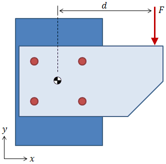
Out-of-Plane Eccentric Shear Load
The figure below shows a pattern with an eccentric shear load that is applied out of the plane of the pattern. While this applied load passes over the centroid in the X-Y plane, its line of action is offset from the centroid in the Z-direction. Therefore, the applied shear load induces a bending moment about the X-axis which results in axial loading on the bolts.

There are several standard approaches to distributing axial loads among the bolts in a case like this, all of which involve calculating the moment of inertia of the pattern about some bending axis and then using (Mr/I)·A to distribute the loads. (It should be noted that if all of the bolts in the pattern are the same size, then (Mr/I)·A simplifies to Mr / Σ r2 ). The key difference in the standard approaches is the selection of the point about which the pattern is assumed to pivot:
- One approach is to inspect the component geometry and to assume that the pattern will "heel" about some reasonable point, say the base of the bracket in the figure above.
-
Another approach is to treat this problem as if the pattern were a beam in bending and to calculate an appropriate location of the neutral axis.
- The methodology outlined in the AISC "Steel Construction Manual" recognizes that on the compression side of the beam, the compressed area is equal to the contact area of the components below the neutral axis. On the tension side of the beam, only the bolts are in tension. The location of the neutral axis is found through an iterative procedure by which the prospective location of the neutral axis is varied until the moment of inertia of the bolts in tension above the neutral axis is equal to the moment of inertia of the compressed plates below the neutral axis.
- A simpler approach considers only the bolt areas and assumes that the neutral axis of the beam lies at the centroid of the bolt pattern.
It is important to recognize that as the assumed pivot location moves farther from the pattern, the axial loads on the bolts are reduced. This fact holds true for all of the approaches outlined above, but it is easiest to recognize when considering the simplified case where the axial loads are directly proportional to Mr / Σ r2. Recall that r is the distance between the pivot location and the bolt of interest. As r increases, the effect of the r2 term in the denominator outpaces the effect of the r term in the numerator. Therefore, the most conservative approach is to consider that the pattern pivots about its centroid.
Generalized Approach
If you decide to take the conservative approach of translating all applied loading to the centroid of the bolt pattern, then it becomes easy to generalize the analysis of any bolt pattern with any applied loading, as in the figure below.

The steps to distribute applied forces and moments to the individual bolted joints in the pattern are:
- Calculate relevant pattern properties (area, centroid, moments of inertia).
- Translate all applied forces and moments to the centroid of the pattern.
- Calculate axial and shear loads acting on individual bolted joints in the pattern.
Details to perform each of these steps are provided in the following sections.
Need a Bolt Pattern Calculator?
Try our bolt pattern force distribution calculator, which allows for applied forces to be distributed over bolts in a pattern.

Bolt Pattern Properties
The same properties that are required when analyzing a beam or a shaft are also required when distributing forces over a bolt pattern. It should be noted that the equations presented in this section for calculating pattern properties do not require the bolts in the pattern to be the same size.
Bolt Pattern Area
The combined area of all bolts in the pattern must be calculated in order to distribute direct forces among the bolts:

where Ai is the tensile stress area of an individual bolt.
Bolt Pattern Centroid
Just as bending stresses in a beam and torsional stresses in a shaft are centered about the neutral axis, moments on a bolt pattern will tend to rotate the pattern about its centroid. The location of the pattern centroid is calculated as:

|

|
where Ai is the bolt area and xi and yi are the x- and y- bolt locations, respectively.
It should be noted that this calculation is directly analogous to the calculation of the centroid of a cross section.
Bolt Pattern Moments of Inertia
The moments of inertia of a bolt pattern indicate the ability of the pattern to resist bending moments. We conservatively assume that moments will tend to cause the pattern to rotate about its centroid, so moments of inertia about the pattern centroid are of interest. The centroidal moments of inertia are calculated as:

|
centroidal moment of inertia about the X-axis |

|
centroidal moment of inertia about the Y-axis |
where Ai is the bolt area and rc.x,i and rc.y,i are the x- and y- distances of the bolt from the pattern centroid, respectively.
The polar moment of inertia of the pattern indicates the pattern's ability to resist torsional moments (i.e., moments about the Z-axis perpendicular to the plane of the pattern), and it is calculated as:

where rc.xy,i is the shortest distance between the bolt and the centroid and is calculated as
 .
.
It should be noted that these calculations are directly analogous to the calculation of the moment of inertia of a cross section and polar moment of inertia of a cross section.
Forces and Moments at Centroid
As discussed previously, all applied forces and moments are translated to the centroid of the bolt pattern. As indicated in the figure below, any number of forces can be applied to the bolt pattern at any location.
The forces at the centroid are calculated as the sum of all applied forces:

The moments at the centroid are calculated as the sum of all applied moments, plus the sum of the cross product of each applied force with the vector from the centroid to the location of that applied force:

In the equations above, the bars over the variables indicate that they are vectors. The variable F is a force vector composed of the force components in each direction: Fx, Fy, and Fz. Likewise, M is a moment vector composed of moments about each axis. R is a location vector specifying the location of an applied force with respect to the pattern centroid. The location vector R points from the centroid to the location of the applied force.
Need a Bolt Pattern Calculator?
Try our bolt pattern force distribution calculator, which allows for applied forces to be distributed over bolts in a pattern.
Forces on Individual Bolted Joints
Once the pattern properties are known and the applied forces and moments have been translated to the pattern centroid, it is possible to calculate the axial and shear forces on the individual bolted joints. The figure below shows an individual bolted joint with applied axial and shear loading:

Axial Forces
The axial forces are a result of the direct force in the Z-direction, Fc.z, the centroidal moment about the X-axis, Mc.x, and the centroidal moment about the Y-axis, Mc.y. These forces and moments are shown as red arrows in the figure below, acting at the centroid of the bolt pattern. The blue arrows indicate the axial reaction forces at each bolted joint. Each blue arrow represents a component of the axial force due to either the direct force in Z, the centroidal moment about X, or the centroidal moment about Y. The calculation of these reaction force components is the subject of this section.

The direct force in the Z-direction, Fc.z, is divided between the individual bolted joints according to the bolt stiffnesses. Because the bolts are all assumed to have the same material and length, the stiffness is dependent only on the tensile stress area of the bolt. The axial force on a bolted joint due to the direct force in Z is calculated as:

where A is the area of the bolt in question. If the bolt areas are the same, the equation above simplifies to Pz.FZ = Fc.z/n, where n is the number of bolts in the pattern.
The axial forces on a bolt due to moments about X- and Y- axes are calculated as:

|
axial force on bolt due to MX about centroid |

|
axial force on bolt due to MY about centroid |
where Mc.x and Mc.y are the centroidal moments about the X- and Y- axes, rc.x and rc.y are the bolt distances from the centroid in the X- and Y-directions, and Ic.x and Ic.y are the pattern moments of inertia about the X- and Y- axes.
If the bolt areas are the same, the equations above simplify to:

|

|
The total axial force on a bolt is the sum of the axial force components:
Shear Forces
The shear forces are a result of the direct force in the X-direction, Fc.x, the direct force in the Y-direction, Fc.y, and the centroidal moment about the Z-axis, Mc.z, as shown in the figure below:

The direct forces in the X- and Y- directions, Fc.x and Fc.y, respectively, are divided between the bolts according to the bolt stiffnesses. Because the bolts are all assumed to have the same material and length, the stiffness is dependent only on area. The shear reactions on a bolt due to the direct forces in X- and Y- are calculated as:

|
X-reaction on bolt due to direct force in X |

|
Y-reaction on bolt due to direct force in Y |
where A is the area of the bolt in question. If the bolt areas are the same, the equations above simplify to Px.FX = Fc.x/n and Py.FY = Fc.y/n, where n is the number of bolts in the pattern.
The shear reaction on a bolt due to moment about the Z-axis is calculated as:

where Mc.z is the centroidal moment about the Z-axis and Ic.p is the pattern's polar moment of inertia. The value rc.xy is the shortest distance between the bolt and the centroid and is calculated as
 .
.
The shear reaction Pxy.MZ is then resolved into X- and Y- components based on the angle θ (see the figure above):
| Px.MZ = Pxy.MZ · sinθ | X-reaction on bolt due to MZ about centroid |
| Py.MZ = −Pxy.MZ · cosθ | Y-reaction on bolt due to MZ about centroid |
The value θ is the angle between the bolt location and the positive X-axis and is calculated as θ = tan-1(rc.y/rc.x).
The total shear reaction on a bolt is calculated as the vector sum of the X- components plus the Y- components:

What's Next?
Now that the axial and shear forces on the individual bolted joints have been calculated, the stresses in the bolted joints can be analyzed as discussed here.
PDH Classroom offers a continuing education course based on this bolt pattern reference page. This course can be used to fulfill PDH credit requirements for maintaining your PE license.
Now that you've read this reference page, earn credit for it!

References
- Barrett, Richard T., "Fastener Design Manual," NASA Reference Publication 1228, 1990.
- Bickford, John, "An Introduction to the Design and Behavior of Bolted Joints," 4th Ed.
- Bruhn, E.F., "Analysis and Design of Flight Vehicle Structures," June 1973.
- Budynas-Nisbett, "Shigley's Mechanical Engineering Design," 8th Ed.
- Lindeburg, Michael R., "Mechanical Engineering Reference Manual for the PE Exam," 13th Ed.
- Niu, Michael C., "Airframe Stress Analysis and Sizing," October 2011.
- "Steel Construction Manual," American Institute of Steel Construction (AISC), 14th Ed.


