Column Buckling Instructions
This page outlines the general use of the Column Buckling calculator.
Reference and Validation
Reference: A general description of the theory and the methodology used can be found here.
Validation: This tool has been validated against the known solutions to numerous example problems. Documentation of the validation can be found here.
Inputs
In this section, all of the relevant details pertaining to the analysis are entered. These inputs relate to the column geometry, material, loading, and end conditions.
The input form is shown below. In this case, a 1 inch circular cross section was specified for the column along with a material of 6061-T6 Aluminum. The column has a 10 inch unsupported length (i.e. it is not braced or supported against buckling) and pinned-pinned end conditions. A force of 10,000 lbf is applied to the column with an eccentricity of 0.1 inches, meaning that the load is applied at 0.1 inches from the central axis of the column.
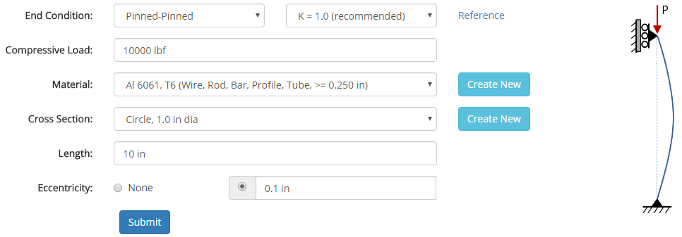
Materials and cross sections are specified in separate sections of this site, and once they are specified they will show up in the drop-down menus on the input form.
If a cross section is chosen that is not symmetric, then the properties for the weakest direction will be used in the analysis.
Once all of the inputs are entered, hitting the 'Submit' button will solve the analysis, and the results will be displayed.
Results
After the analysis is solved, results are displayed in multiple tabs. Each results tab is discussed in the following sections.
Results Summary
A summary of the results is provided to give a high-level overview of the factors of safety and the critical values for the column.
Properties
After the analysis is solved, properties relevant to the analysis are displayed. These properties include material properties, cross section properties, and column properties related to buckling.
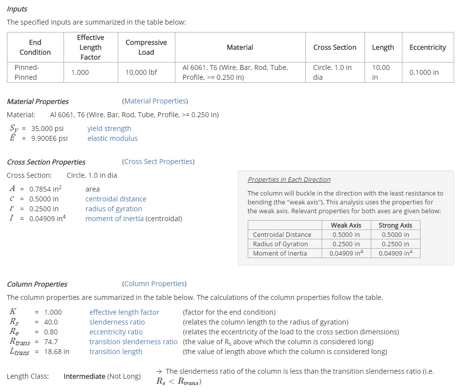
The way in which these properties are used in the analysis is described in more detail in the Reference section.
Results Details
The results of the analysis consist of plots as well as numerical results. The full results section is long, but the highlights are provided here.
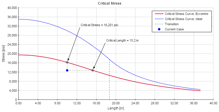
The Critical Stress plot is shown below. This plot shows the current case (i.e. the length and average stress in the column) in relation to the Critical Stress Curve. If the column is not loaded eccentrically, then only the ideal curve will be displayed. In this case, the point representing the current case must lie below the ideal curve in order to have a Factor of Safety (FS) greater than 1. However, if the column is loaded eccentrically then both the ideal curve and the eccentric curve will be displayed. In this case, the point representing the current case must lie below the eccentric curve in order to have a FS greater than 1.
The ideal curve is a combination of the Euler curve (for lengths above the transition length) and the Johnson parabola (for lengths below the transition length). The eccentric curve is calculated based on the Secant Formula. More details on this can be found in the Reference section.
It should be noted in the plot that a vertical line is drawn between the current case and the critical stress curve with an intersection point denoted "Critical Stress." This point indicates the maximum average stress that could exist in the column before buckling would occur. Likewise, a horizontal line is drawn between the current case and the critical stress curve with an intersection point denoted "Critical Length." This point indicates the maximum unsupported length that could exist in the column before buckling would occur.
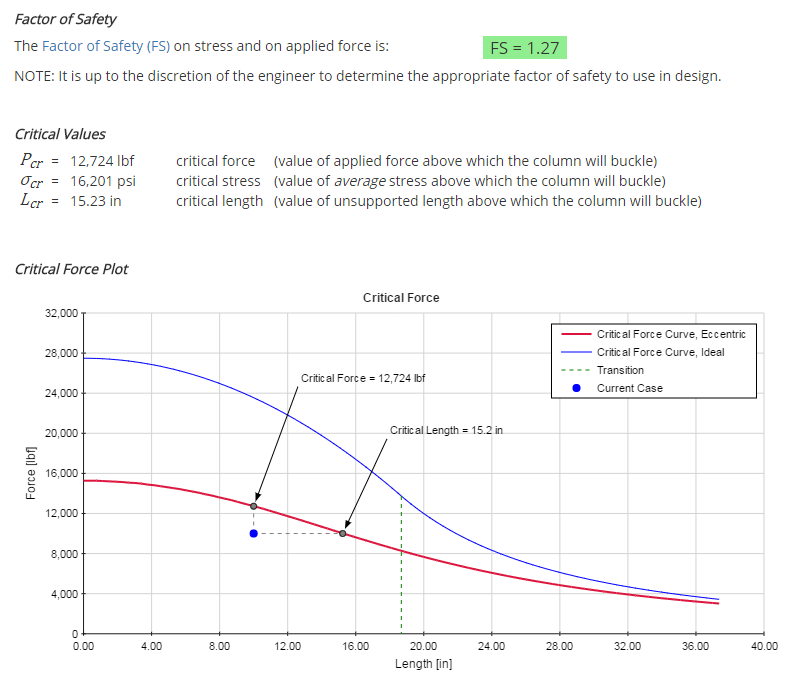
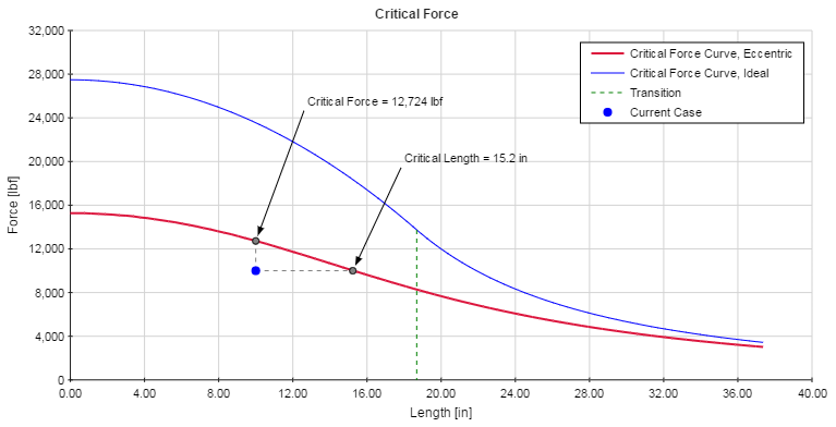
The Critical Force plot is shown below. This plot is the same as the Critical Stress plot, with the exception being that force is plotted along the Y-axis instead of average stress.
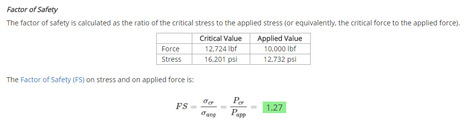
The factor of safety is calculated as shown below. The applied values are compared to the critical values, which are the values that will result in buckling of the column. A factor of safety greater than 1 is required for the column not to buckle; however, a margin should be employed to ensure adequate safety. It is up to the discretion of the engineer to determine the appropriate factor of safety to use in design.