Bolt Pattern Force Distribution Instructions
This page outlines the general use of the Bolt Pattern Force Distribution calculator. This calculator allows you to specify the geometry of a bolt pattern, apply forces and moments to the pattern, and then solve to calculate the resultant axial and shear forces on each individual bolt in the pattern.
Reference and Validation
Reference: A general description of the theory and the methodology used can be found here.
Validation: This tool has been validated against the known solutions to numerous example problems. Documentation of the validation can be found here.
Inputs
Two categories of inputs are entered:
- Bolt pattern geometry
- Applied forces
Each input category has a dedicated tab in the interface. Each of these tabs will be discussed in the following sections.
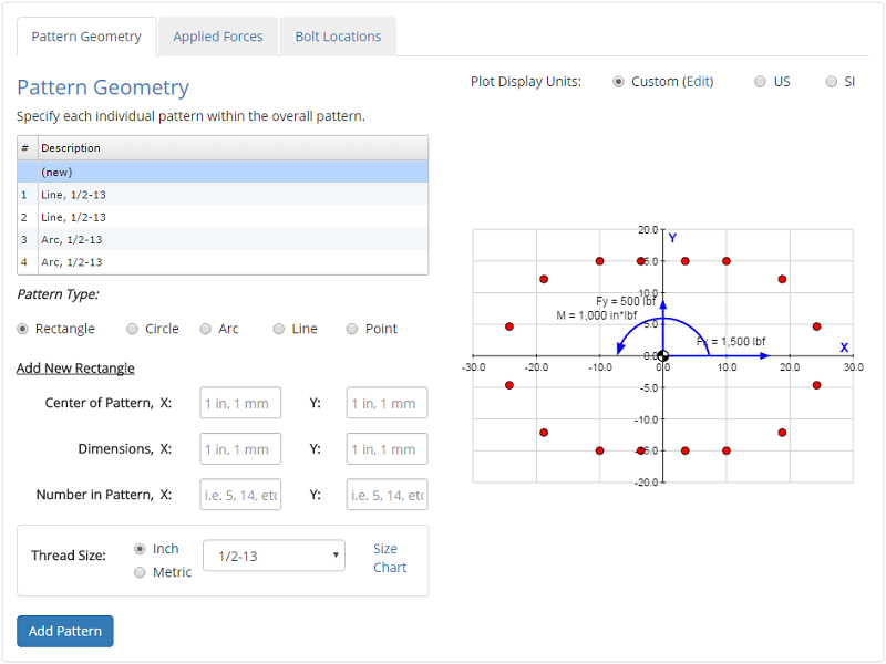
Bolt Pattern Geometry
In the Pattern Geometry tab you specify the geometry of the bolt pattern. The geometry of the pattern includes the location and thread size of each bolt.
To simply the process of specifying bolt locations, several pattern geometries are made available to you:
| • | Rectangle: | Specify the bolts along a rectangle. The rectangle is defined by a center point, a width, and a height. |
| • | Circle: | Specify bolts along a circle. The circle is defined by a center point, a diameter, and a start angle (so that you can orient the first bolt). |
| • | Arc: | Specify bolts along an arc. The arc is defined by a center point, a radius, and start and end angles. |
| • | Line: | Specify bolts along a line. The line is defined by its end points. |
| • | Point: | Specify the location of an individual bolt. |
Thread size is also specified. The thread size determines the bolt area, which affects the properties of the overall pattern (i.e. centroid, moment of inertia) as well as the proportion of the load carried by an individual bolt.
The Pattern Geometry input tab is shown below:
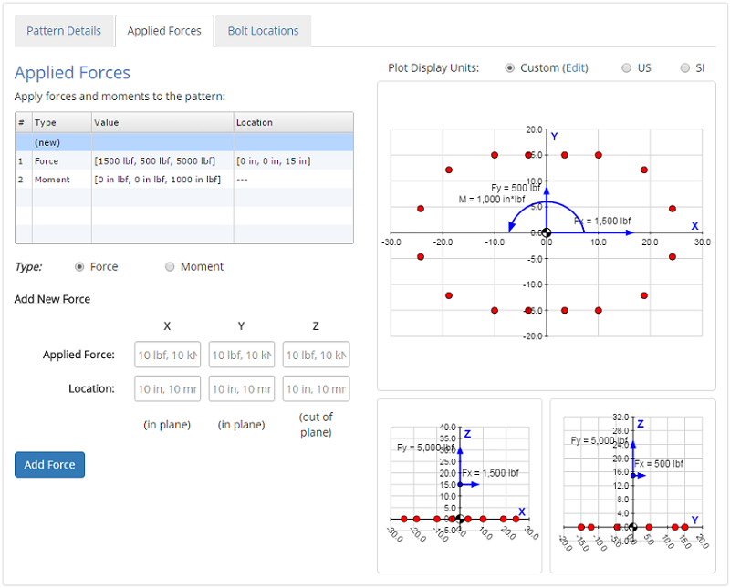
Applied Forces
In the Applied Forces tab you specify the forces and moments that are applied to the pattern.
For applied forces, the location of the force also needs to be spcified in addition to the force value itself. The force can be located anywhere in 3D space. Note that the pattern itself lies in the X-Y plane. Using the location of the applied force, the moments at the centroid due to the force can be calculated using \( M = R \times F \).
The Applied Forces input tab is shown below:
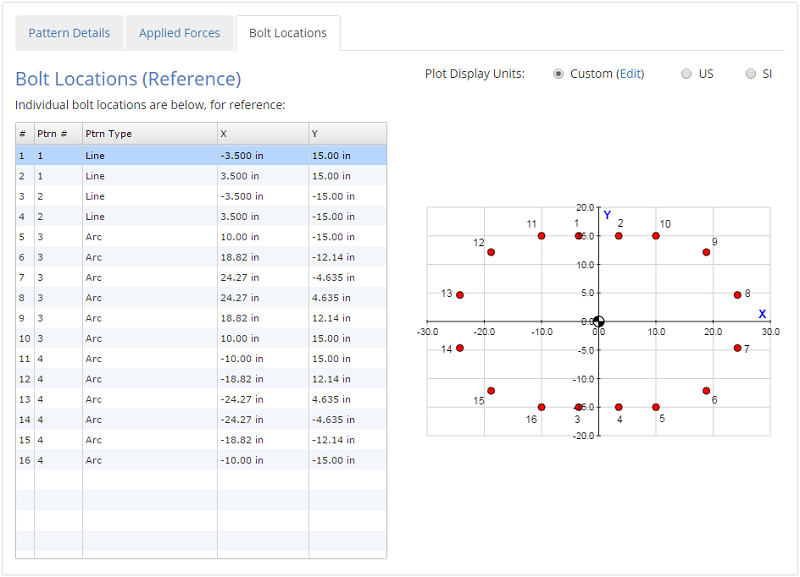
Bolt Locations
In the Bolt Locations tab, you can see the locations of each bolt in the pattern. This tab is provided for reference only, and does not actually require any input from the user.
Once all of the inputs are entered, hitting the 'Submit' button will solve the analysis, and the results will be displayed.
Results
After the analysis is solved, results are displayed in multiple tabs. Each results tab is discussed in the following sections.
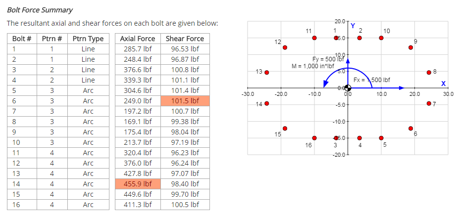
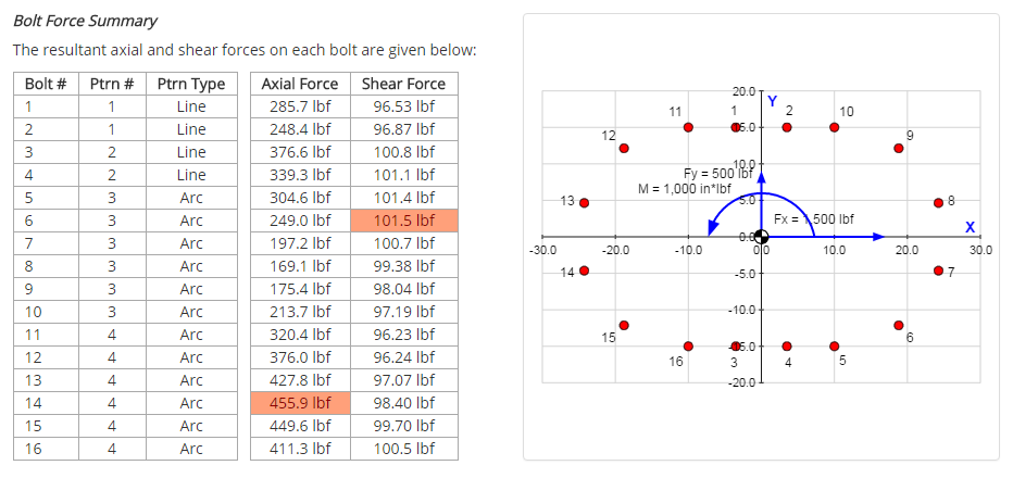
Results Summary
A summary of the results is provided to give a high-level overview of the primary results of interest:
- Individual bolt forces
- Forces & moments at the pattern centroid
- Pattern properties (i.e. combined area, centroid location, moments of inertia)
A view of a portion of the summary tab for an example problem is shown below:
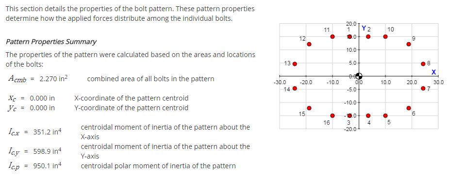
Pattern Properties
The Pattern Properties tab displays the properties of the pattern that determine how the applied forces distribute among the individual bolts. These properties include:
- Combined area of all bolts in the pattern
- Pattern centroid location
- Centroidal moments of inertia of the pattern
The equations used to calculate the pattern properties are given along with the results. More details on the methodology used to calculate the pattern properties can be found in the Reference section.
A view of a portion of the properties tab for an example problem is shown below:
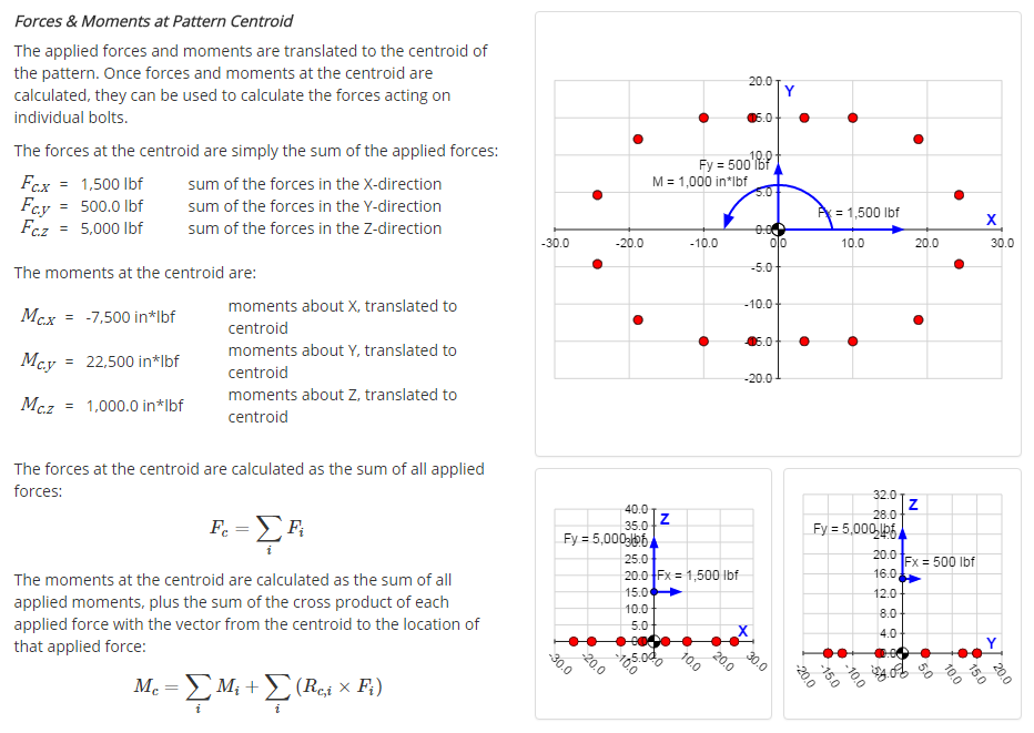
Forces at Centroid
This tab shows how the applied forces and moments are translated to the centroid of the pattern, and it gives the calculated values of the forces and moments at the centroid.
A view of a portion of the forces tab for an example problem is shown below:
Individual Bolt Forces
This tab details the calculation of the resultant axial and shear forces acting on each individual bolt.
A view of a portion of the bolt forces tab for an example problem is shown below: