Column Buckling
The Column Buckling calculator allows for buckling analysis of long and intermediate-length columns loaded in compression. The loading can be either central or eccentric. See the instructions within the documentation for more details on performing this analysis. See the reference section for details on the equations used.
Inputs
Input the details for the column, then click the "Calculate Results" button:
Display Units
Display results in:
Results
The results of the column buckling analysis are detailed below. Refer to the column buckling analysis reference section for details on how these results were derived.
Results Summary
A summary of the results is shown below. Further details are given on the other tabs.
Factor of Safety
The Factor of Safety (FS) on stress and on applied force is:
| FS = |
NOTE: It is up to the discretion of the engineer to determine the appropriate factor of safety to use in design.
Critical Values
| Pcr | = | critical force | (value of applied force above which the column will buckle) | |
| σcr | = | critical stress | (value of average stress above which the column will buckle) | |
| Lcr | = | critical length | (value of unsupported length above which the column will buckle) |
Critical Force Plot
See full result details on the other tabs (above).
Column Properties
This section details the properties of the column material and geometry based on the provided inputs.
Inputs
The specified inputs are summarized in the table below:
| End Condition | Effective Length Factor |
Compressive Load |
Material | Cross Section | Length | Eccentricity |
|---|---|---|---|---|---|---|
Material Properties
| Material: |
| Sy | = | yield strength | |
| E | = | elastic modulus |
Cross Section Properties
| Cross Section: |
| A | = | area | |
| c | = | centroidal distance | |
| r | = | radius of gyration | |
| I | = | moment of inertia (centroidal) |
Properties in Each Direction
The column will buckle in the direction with the least resistance to bending (the "weak axis"). This analysis uses the properties for the weak axis. Relevant properties for both axes are given below:
| Weak Axis | Strong Axis | |
|---|---|---|
| Centroidal Distance | ||
| Radius of Gyration | ||
| Moment of Inertia |
Column Properties
The column properties are summarized in the table below. The calculations of the column properties follow the table.
| K | = | effective length factor | (factor for the end condition) | |
| Rs | = | slenderness ratio | (relates the column length to the radius of gyration) | |
| Re | = | eccentricity ratio | (relates the eccentricity of the load to the cross section dimensions) | |
| Rtrans | = | transition slenderness ratio | (the value of Rs above which the column is considered long) | |
| Ltrans | = | transition length | (the value of length above which the column is considered long) |
| Length Class: | Long | → | The slenderness ratio of the column is greater than the transition slenderness ratio (i.e. Rs ≥ Rtrans) |
| Length Class: | Intermediate (Not Long) | → | The slenderness ratio of the column is less than the transition slenderness ratio (i.e. Rs < Rtrans) |
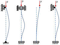
The effective length factor, K, is based on the end condition:
| → | K = |
The slenderness ratio of this column is:
| Rs = L/r = |
Reference Values
| L | = | |
| r | = |
The eccentricity ratio of this column is:
|
|
Reference Values
| e | = | |
| c | = | |
| r | = |
The transition slenderness ratio is calculated below. A column with a slenderness ratio above this value is considered long:
|
|
Reference Values
| K | = | |
| Sy | = | |
| E | = |
The transition length is calculated below. This is the length above which the column is considered long:
| Ltrans = Rtransr = |
Reference Values
| Rtrans | = | |
| r | = |
The slenderness ratio of the column is greater than the transition slenderness ratio (i.e. Rs ≥ Rtrans). Likewise, the length of the column is greater than the transition length (i.e. L ≥ Ltrans).
→ this column is long
The slenderness ratio of the column is less than the transition slenderness ratio (i.e. Rs < Rtrans). Likewise, the length of the column is less than the transition length (i.e. L < Ltrans).
→ this column is of intermediate length (not long)
Reference Values
| Rs | = | |
| Rtrans | = | |
| L | = | |
| Ltrans | = |
Results Details
This section details the column results. Refer to the column buckling reference for details further on how these results were derived.
Long Column with Central Load
Since this is a long column with a centrally applied load, the Euler formula is used to calculate the critical stress:
|
|
Reference Values
| E | = | |
| K | = | |
| L | = | |
| r | = |
The critical force corresponding to the critical stress above is:
| Pcr = σcr A = |
Reference Values
| σcr | = | |
| A | = |
Intermediate Column with Central Load
Since this is an intermediate column with a centrally applied load, the Johnson formula is used to calculate the critical stress:
|
|
Reference Values
| Sy | = | |
| E | = | |
| K | = | |
| L | = | |
| r | = |
The critical force corresponding to the critical stress above is:
| Pcr = σcr A = |
Reference Values
| σcr | = | |
| A | = |
Column with Eccentric Load
Since this column has an eccentric load, the secant formula is used to calculate the critical force. The critical force is found by iterating the force value, P, until the calculated maximum compressive stress equals the compressive yield strength of the material (in this case, Sy = ). At a force of P = , the maximum compressive stress in the column is:
|
|
Therefore, we can conclude that the critical force is:
| Pcr = |
Reference Values
| P | = | |
| Sy | = | |
| E | = | |
| K | = | |
| A | = | |
| L | = | |
| e | = | |
| r | = | |
| c | = |
The critical stress is the average compressive stress above which the column buckles, and is calculated as:
|
|
Reference Values
| Pcr | = | |
| A | = |
Critical Force Plot
The plot below shows the critical force as a function of column length. The critical force is the compressive force above which the column will buckle.
The critical force curve is calculated using the Euler formula for long columns and the Johnson formula for intermediate columns. The Euler formula is used above the transition point, and the Johnson formula below.
There are two critical curves shown in this plot. The ideal critical curve is calculated using the Euler formula for long columns and the Johnson formula for intermediate columns (the Euler formula is used above the transition point, and the Johnson formula below). The eccentric critical curve is calculated using the secant formula. Note that the eccentric curve is lower than the ideal curve, so that the column buckles at a lower applied load.
Critical Stress Plot
The plot below shows the critical stress as a function of column length. The critical stress is the value of average compressive stress above which the column will buckle, where the average stress is calculated simply as σ = P/A.
Critical Values
As the column length increases, it becomes more susceptible to buckling. The critical length is the length above which the column will buckle. The critical length, read from the plots above, is:
| Lcr = |
The critical values of force and stress were calculated previously, but are given below for reference:
| Pcr | = | critical force | (value of applied force above which the column will buckle) | |
| σcr | = | critical stress | (value of average stress above which the column will buckle) | |
| Lcr | = | critical length | (value of unsupported length above which the column will buckle) |
Current Values
The current values of interest (based on applied loads and column geometry) are required in order to determine the factor of safety.
The applied compressive force and the column unsupported length were specified as inputs:
| Papp | = | applied compressive force | |
| L | = | length (unsupported) |
The average compressive stress in the column is calculated as:
|
|
Reference Values
| Papp | = | |
| A | = |
Current Values for Eccentric Loading
Since the loading on this column is eccentric, there are a couple more values of interest to calculate.
The maximum deflection in the column is calculated as:
|
|
The maximum compressive stress in the column is calculated as:
|
|
Reference Values
| P | = | |
| E | = | |
| K | = | |
| A | = | |
| L | = | |
| e | = | |
| r | = | |
| c | = |
Factor of Safety
The factor of safety is calculated as the ratio of the critical stress to the applied stress (or equivalently, the critical force to the applied force).
| Critical Value | Applied Value | |
|---|---|---|
| Force | ||
| Stress |
The Factor of Safety (FS) on stress and on applied force is:
|
|
Download Report
Save a formatted Word document to your computer detailing the inputs and results of the analysis.
Download Inputs File
Save all input data to a file. You can later upload this file to pick back up where you left off.
Need More Functionality?
Sign up for an account to receive full access to all calculators and other content. The subscription types are described below, along with the benefits of each.
- Price
- Access to Calculators
- Login
- Create Materials
- Create Cross Sections
- Save Files
- Reporting
- Free
-
LimitedLimited Access to Calculators
-
NoneNo Login
-
Pre-defined Materials
-
Pre-defined Cross Sections
-
No Saved Files
-
No Reporting
- Learn More »
-
USD $9.99 /month USD $99.99 /year -
FullFull Access to Calculators
-
IndividualIndividual Login
-
Create Materials
-
Create Cross Sections
-
Unlimited Saved Files
-
Unlimited Reporting
- Learn More »
- Sign Up Now
-
USD $29.99 /month USD $299.99 /year -
FullFull Access to Calculators
-
Floating LicensesFloating Licenses
-
Create Materials
-
Create Cross Sections
-
Unlimited Saved Files
-
Unlimited Reporting
- Learn More »
- Sign Up Now
-
Bulk pricing (≥20 educational licenses)
-
FullFull Access to Calculators
-
Floating LicensesFloating Licenses
-
Create Materials
-
Create Cross Sections
-
Unlimited Saved Files
-
Unlimited Reporting
- Learn More »
- Sign Up Now
Solving, please wait...

Looking for Other Calculators?
Here are just a few of the calculators that we have to offer:
Feedback
Do you have any comments or suggestions? We would love to hear them!
