Cross Sections
The behavior of a structural member is dictated by its material and its geometry. This reference is focused on the influence of geometry on the behavior of a structural member. The cross section and the length of the structural member affect how much that member deflects under a load, and the cross section determines the stresses that exist in the member under a given load.
Properties of Areas
Centroid
The centroid of a shape represents the point about which the area of the section is evenly distributed. If the area is doubly symmetric about two orthogonal axes, the centroid lies at the intersection of those axes. If the area is symmetric about only one axis, then the centroid lies somewhere along that axis (the other coordinate will need to be calculated). If the exact location of the centroid cannot be determined by inspection, it can be calculated by:
|
|
|
where dA represents the area of an infinitesimally small element, A is the total area of the cross section, and x and y are the coordinates of element dA with respect to the axis of interest.
The centroidal locations of common cross sections are well documented, so it is typically not necessary to calculate the location with the equations above.
If a cross section is composed of a collection of basic shapes whose centroidal locations are known with respect to some reference point, then the centroidal location of the composite cross section can be calculated as:
|
|
|
where xc,i and yc,i are the rectangular coordinates of the centroidal location of the ith section with respect to the reference point, and Ai is the area of the ith section.
Centroidal Distance
The centroidal distance, c, is the distance from the centroid of a cross section to the extreme fiber. The centroidal distance in the y-direction for a rectangular cross section is shown in the figure below:
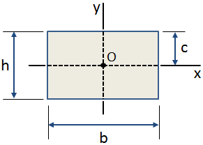
Common uses for centroidal distance include:
- calculating the maximum bending stress in a cross section
- calculating the value of the first moment of area, Q, above a point in the cross section to determine the shear stress at that point
We have a number of structural calculators to choose from. Here are just a few:
First Moment of Area
The first moment of area indicates the distribution of an area with respect to some axis. The first moment of an area with respect to an axis of interest is calculated as:
| Qx = ∫ y dA | Qy = ∫ x dA |
where Qx is the first moment about the x-axis and Qy is the first moment about the y-axis. The values x and y indicate the locations with respect to the axis of interest of the infinitesimally small areas, dA, of each element as the integration is performed.
If the area is composed of a collection of basic shapes whose centroidal locations are known with respect to the axis of interest, then the first moment of the composite area can be calculated as:
|
|
|
If you compare the equations for Q above to the equations for calculating the centroid (discussed in a previous section), you will see that we actually use the first moment of area when calculating the centroidal location with respect to an origin of interest.
The first moment is also used when calculating the value of shear stress at a particular point in the cross section. Recall that the shear stress at any point located a distance y1 from the centroid of the cross section is calculated as:
where Q is the first moment of the area between the point y1 and the extreme fiber (top or bottom) of the cross section. Consider the figure below. We are interested in calculating the shear stress at a point located at a distance y1 from the centroid of the cross section. We may calculate the first moment of the area either above or below this location. In this case the point of interest is above the neutral axis, so it is simpler to consider the upper area which is shaded in blue in the figure below. This area extends from the point y1 to the extreme fiber at the top of the cross section.
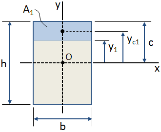
The first moment about the x-axis of the area shaded in blue in the figure above is calculated with respect to the centroid of the cross section (point O in the figure) as:
If the centroidal location of the area of interest is known, then the first moment of the area with respect to the centroid simplifies to (refer to the figure above):
It should be noted that the first moment of an area is either positive or negative depending on the position of the area with respect to the axis of interest. Therefore, the first moment of the entire area of a cross section with respect to its own centroid is zero.
Area Moment of Inertia
The second moment of area, more commonly known as the moment of inertia, I, of a cross section is an indication of a structural member's ability to resist bending.(Note 1) Ix and Iy are the moments of inertia about the x- and y- axes, respectively, and are calculated by:
| Ix = ∫ y2 dA | Iy = ∫ x2 dA |
where x and y are the coordinates of element dA with respect to the axis of interest.
Most commonly, the moments of inertia are calculated with respect to the section's centroid. In this case they are referred to as centroidal moments of inertia and are denoted as Icx for the inertia about the x-axis and Icy for the inertia about the y-axis.
The moments of inertia of common cross sections are well documented, so it is typically not necessary to calculate them with the equations above. Properties of several common cross sections are given at the end of this page.
If a cross section is composed of a collection of basic shapes whose centroids are all coincident, then the moment of inertia of the composite section is simply the sum of the individual moments of inertia. An example of this is a box beam that consists of two rectangular sections, as shown below. In this case, the outer section has "positive area" and the inner section has "negative area," so the composite moment of inertia is the subtraction of the moment of inertia of the inner section from the outer section.
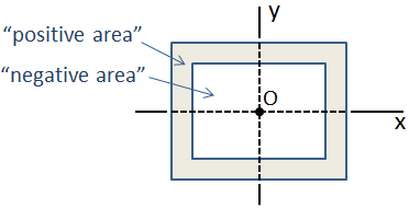
In the case of a more complicated composite cross section in which the centroidal locations are not coincident, the moment of inertia can be calculated using the parallel axis theorem.
It is important not to confuse the moment of inertia of an area with the mass moment of inertia of a solid body. The area moment of inertia indicates a cross section's resistance to bending, whereas the mass moment of inertia indicates a body's resistance to rotation.
We have a number of structural calculators to choose from. Here are just a few:
Parallel Axis Theorem
If the moment of inertia of a cross section about a centroidal axis is known, then the parallel axis theorem can be used to calculate the moment of inertia about any parallel axis:
where Ic is the moment of inertia about the centroidal axis, d is the distance between the centroidal axis and the parallel axis, and A is the area of the cross section.
If a cross section is composed of a collection of basic shapes whose centroidal moments of inertia are known along with the distances of the centroids to some reference point, then the parallel axis theorem can be used to calculate moment of inertia of the composite cross section.
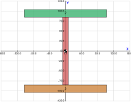
For example, an I-Beam can be approximated by 3 rectangles, as shown below. Since this composite section is symmetric about both the x- and y- axes, the centroid of the section can be located by inspection at the intersection of those axes. The centroid is located at the origin, O, in the figure.
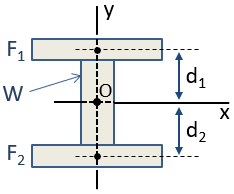
The moment of inertia of the composite section can be calculated by using the parallel axis theorem. The section's centroidal moment of inertia about the x-axis, Icx, is calculated as:
where the Icx terms are the moments of inertia of the individual sections about their own centroids in the orientation of the x-axis, the d terms are the distances of the individual section centroids to the composite section centroid, and the A terms are the areas of the individual sections. Because the centroid of section W and the centroid of the composite section are coincident, d is zero for that section and so there is no Ad2 term.
It is important to note the implication of the parallel axis theorem that as an individual section moves farther from the centroid of the composite section, the contribution of that section to the composite section's moment of inertia increases by a factor of d2. Therefore, if the intent is to increase the moment of inertia of a section about a particular axis, it is most efficient to locate the area as far from that axis as possible. This explains the shape of an I-Beam. The flanges are the primary contributors to the moment of inertia, and the web serves to separate the flanges from the bending axis. The web does need to maintain some thickness however to avoid buckling, and because the web takes a significant portion of the shear stress in the section.
Polar Moment of Inertia
The polar moment of inertia, J, of a cross section is an indication of a structural member's ability to resist torsion about an axis perpendicular to the section. The polar moment of inertia for a section with respect to an axis can be calculated by:
where x and y are the coordinates of element dA with respect to the axis of interest, and r is the distance between the element dA and the axis of interest.
Although the polar moment of inertia can be calculated using the equation above, it is typically more convenient to calculate it using the perpendicular axis theorem, which states that the polar moment of inertia of an area is the sum of the moments of inertia about any two orthogonal axes that pass through the axis of interest:
Most commonly, the axis of interest passes through the centroid of the cross section.
Section Modulus
The maximum bending stress in a beam is calculated as σb = Mc / Ic, where c is the distance from the neutral axis to the extreme fiber, Ic is the centroidal moment of inertia, and M is the bending moment. The section modulus combines the c and Ic terms in the bending stress equation:
Using the section modulus, the bending stress is calculated as σb = M / S. The utility of the section modulus is that it characterizes the bending resistance of a cross section in a single term. This allows for optimization of a beam's cross section to resist bending by maximizing a single parameter.
Radius of Gyration
The radius of gyration represents the distance from a section's centroid at which all of the area could be concentrated without having any effect on the moment of inertia. The radius of gyration of a shape with respect to each axis is given by:
|
|
|
A polar radius of gyration can also be calculated for problems involving torsion about a centroidal axis:
The rectangular radii of gyration can also be used to calculate the polar radius of gyration:
PDH Classroom offers a continuing education course based on this cross sections reference page. This course can be used to fulfill PDH credit requirements for maintaining your PE license.
Now that you've read this reference page, earn credit for it!
Properties of Common Cross Sections
The table below gives properties of common cross sections. More extensive tables can be found in the listed references.
The properties calculated in the table include area, centroidal moment of inertia, section modulus, and radius of gyration.
| Shape | Representation | Properties | |||||||
|---|---|---|---|---|---|---|---|---|---|
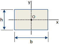
| Rectangle |
|
Area [in2]:
Moment of Inertia [in4]:
Section Modulus [in3]:
Radius of Gyration [in]:
|
|||||||
| Circle |
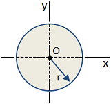
|
Area [in2]:
Moment of Inertia [in4]:
Section Modulus [in3]:
Radius of Gyration [in]:
|
|||||||
| Circular Tube |
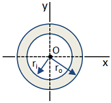
|
Area [in2]:
Moment of Inertia [in4]:
Section Modulus [in3]:
Radius of Gyration [in]:
|
|||||||
| I-Beam |
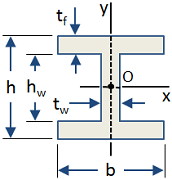
|
Area [in2]:
Moment of Inertia [in4]:
Section Modulus [in3]:
|
We have a number of structural calculators to choose from. Here are just a few:
Notes
Note 1: Deflection of a Beam
The deflection of a beam under bending is determined by the moment of inertia of the cross section, the length of the beam, and the elastic modulus of the material. More details are given in this discussion of beam deflection.
