


Stresses & Deflections in Beams
Many structures can be approximated as a straight beam or as a collection of straight beams. For this reason, the analysis of stresses and deflections in a beam is an important and useful topic.
This section covers shear force and bending moment in beams, shear and moment diagrams, stresses in beams, and a table of common beam deflection formulas.
Contents
Constraints and Boundary Conditions
For a beam to remain in static equilibrium when external loads are applied to it, the beam must be constrained. Constraints are defined at single points along the beam, and the boundary condition at that point determines the nature of the constraint. The boundary condition indicates whether the beam is fixed (restrained from motion) or free to move in each direction. For a 2-dimensional beam, the directions of interest are the x-direction (axial direction), y-direction (transverse direction), and rotation. For a constraint to exist at a point, the boundary condition must indicate that at least one direction is fixed at that point.
Common boundary conditions are shown in the table below. For each boundary condition, the table indicates whether the beam is fixed or free in each direction at the point where the boundary condition is defined.
| Boundary Condition | Direction | ||
|---|---|---|---|
| Axial (X) | Transverse (Y) | Rotation | |
| Free | Free | Free | Free |
| Fixed | Fixed | Fixed | Fixed |
| Pinned | Fixed | Fixed | Free |
| Guided along X | Free | Fixed | Fixed |
| Guided along Y | Fixed | Free | Fixed |
| Roller along X | Free | Fixed | Free |
| Roller along Y | Fixed | Free | Free |
If the boundary condition indicates that the beam is fixed in a specific direction, then an external reaction in that direction can exist at the location of the boundary condition. For example, if a beam is fixed in the y-direction at a specific point, then a transverse (y) external reaction force may develop at that point. Likewise, if the beam is fixed against rotation at a specific point, then an external reaction moment may develop at that point.
Based on the above discussion, we can see that a fixed boundary condition can develop axial and transverse reaction forces as well as a moment. Likewise, we see that a pinned boundary condition can develop axial and transverse reaction forces, but it cannot develop a reaction moment.
Notice the Free boundary condition in the table above. This boundary condition indicates that the beam is free to move in every direction at that point (i.e., it is not fixed or constrained in any direction). Therefore, a constraint does not exist at this point. This highlights the subtle difference between a constraint and a boundary condition. A boundary condition indicates the fixed/free condition in each direction at a specific point, and a constraint is a boundary condition in which at least one direction is fixed.
Shear Force and Bending Moment
To find the shear force and bending moment over the length of a beam, first solve for the external reactions at each constraint. For example, the cantilever beam below has an applied force shown as a red arrow, and the reactions are shown as blue arrows at the fixed boundary condition.

The external reactions should balance the applied loads such that the beam is in static equilibrium. After the external reactions have been solved for, take section cuts along the length of the beam and solve for the internal reactions at each section cut. (The reaction forces and moments at the section cuts are called internal reactions because they are internal to the beam.) An example section cut is shown in the figure below:

When the beam is cut at the section, either side of the beam may be considered when solving for the internal reactions. The side that is selected does not affect the results, so choose whichever side is easiest. In the figure above, the side of the beam to the right of the section cut was selected. The selected side is shown as the blue section of beam, and section shown in grey is ignored. The internal reactions at the section cut are shown with blue arrows. The reactions are calculated such that the section of beam being considered is in static equilibrium.
Sign Convention
The signs of the shear and moment are important. The sign is determined after a section cut is taken and the reactions are solved for the portion of the beam to one side of the cut. The shear force at the section cut is considered positive if it causes clockwise rotation of the selected beam section, and it is considered negative if it causes counter-clockwise rotation. The bending moment at the section cut is considered positive if it compresses the top of the beam and elongates the bottom of the beam (i.e., if it makes the beam "smile").
Based on this sign convention, the shear force at the section cut for the example cantilever beam in the figure above is positive since it causes clockwise rotation of the selected section. The moment is negative since it compresses the bottom of the beam and elongates the top (i.e., it makes the beam "frown").
The figure below shows the standard sign convention for shear force and bending moment. The forces and moments on the left are positive, and those on the right are negative.

Check out our beam calculator based on the methodology described here.
- Calculates stresses and deflections in straight beams
- Builds shear and moment diagrams
- Can specify any configuration of constraints, concentrated forces, and distributed forces

Shear and Moment Diagrams
The shear force and bending moment throughout a beam are commonly expressed with diagrams. A shear diagram shows the shear force along the length of the beam, and a moment diagram shows the bending moment along the length of the beam. These diagrams are typically shown stacked on top of one another, and the combination of these two diagrams is a shear-moment diagram. Shear-moment diagrams for some common end conditions and loading configurations are shown within the beam deflection tables at the end of this page. An example of a shear-moment diagram is shown in the following figure:

General rules for drawing shear-moment diagrams are given in the table below. All of the rules in this table are demonstrated in the figure above.
| Shear Diagram | Moment Diagram |
|---|---|
|
|

Bending Stresses in Beams
The bending moment, M, along the length of the beam can be determined from the moment diagram. The bending moment at any location along the beam can then be used to calculate the bending stress over the beam's cross section at that location. The bending moment varies over the height of the cross section according to the flexure formula below:

where M is the bending moment at the location of interest along the beam's length, Ic is the centroidal moment of inertia of the beam's cross section, and y is the distance from the beam's neutral axis to the point of interest along the height of the cross section. The negative sign indicates that a positive moment will result in a compressive stress above the neutral axis.
The bending stress is zero at the beam's neutral axis, which is coincident with the centroid of the beam's cross section. The bending stress increases linearly away from the neutral axis until the maximum values at the extreme fibers at the top and bottom of the beam.
The maximum bending stress occurs at the extreme fiber of the beam and is calculated as:

where c is the centroidal distance of the cross section (the distance from the centroid to the extreme fiber).
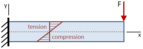
If the beam is asymmetric about the neutral axis such that the distances from the neutral axis to the top and to the bottom of the beam are not equal, the maximum stress will occur at the farthest location from the neutral axis. In the figure below, the tensile stress at the top of the beam is larger than the compressive stress at the bottom.

The section modulus of a cross section combines the centroidal moment of inertia, Ic, and the centroidal distance, c:

The benefit of the section modulus is that it characterizes the bending resistance of a cross section in a single term. The section modulus can be substituted into the flexure formula to calculate the maximum bending stress in a cross section:

Check out our beam calculator based on the methodology described here.
- Calculates stresses and deflections in straight beams
- Builds shear and moment diagrams
- Can specify any configuration of constraints, concentrated forces, and distributed forces
Shear Stresses in Beams
The shear force, V, along the length of the beam can be determined from the shear diagram. The shear force at any location along the beam can then be used to calculate the shear stress over the beam's cross section at that location. The average shear stress over the cross section is given by:

The shear stress varies over the height of the cross section, as shown in the figure below:

The shear stress is zero at the free surfaces (the top and bottom of the beam), and it is maximum at the centroid. The equation for shear stress at any point located a distance y1 from the centroid of the cross section is given by:

where V is the shear force acting at the location of the cross section, Ic is the centroidal moment of inertia of the cross section, and b is the width of the cross section. These terms are all constants. The Q term is the first moment of the area bounded by the point of interest and the extreme fiber of the cross section:

Shear stresses for several common cross sections are discussed in the sections below.
Shear Stresses in Rectangular Sections
The distribution of shear stress along the height of a rectangular cross section is shown in the figure below:

The first moment of area at any given point y1 along the height of the cross section is calculated by:

The maximum value of Q occurs at the neutral axis of the beam (where y1 = 0):

The shear stress at any given point y1 along the height of the cross section is calculated by:

where Ic = b·h3/12 is the centroidal moment of inertia of the cross section. The maximum shear stress occurs at the neutral axis of the beam and is calculated by:

where A = b·h is the area of the cross section.
We can see from the previous equation that the maximum shear stress in the cross section is 50% higher than the average stress V/A.
Shear Stresses in Circular Sections
A circular cross section is shown in the figure below:

The equations for shear stress in a beam were derived using the assumption that the shear stress along the width of the beam is constant. This assumption is valid at the centroid of a circular cross section, although it is not valid anywhere else. Therefore, while the distribution of shear stress along the height of the cross section cannot be readily determined, the maximum shear stress in the section (occurring at the centroid) can still be calculated. The maximum value of first moment, Q, occurring at the centroid, is given by:

The maximum shear stress is then calculated by:

where b = 2r is the diameter (width) of the cross section, Ic = πr4/4 is the centroidal moment of inertia, and A = πr2 is the area of the cross section.
Shear Stresses in Circular Tube Sections
A circular tube cross section is shown in the figure below:

The maximum value of first moment, Q, occurring at the centroid, is given by:

The maximum shear stress is then calculated by:

where b = 2 (ro − ri) is the effective width of the cross section, Ic = π (ro4 − ri4) / 4 is the centroidal moment of inertia, and A = π (ro2 − ri2) is the area of the cross section.
Shear Stresses in I-Beams
The distribution of shear stress along the web of an I-Beam is shown in the figure below:

The equations for shear stress in a beam were derived using the assumption that the shear stress along the width of the beam is constant. This assumption is valid over the web of an I-Beam, but it is invalid for the flanges (specifically where the web intersects the flanges). However, the web of an I-Beam takes the vast majority of the shear force (approximately 90% - 98%, according to Gere), and so it can be conservatively assumed that the web carries all of the shear force.
The first moment of the area of the web of an I-Beam is given by:

The shear stress along the web of the I-Beam is given by:

where tw is the web thickness and Ic is the centroidal moment of inertia of the I-Beam:

The maximum value of shear stress occurs at the neutral axis ( y1 = 0 ), and the minimum value of shear stress in the web occurs at the outer fibers of the web where it intersects the flanges y1 = ±hw/2 ):


PDH Classroom offers a continuing education course based on this beam analysis reference page. This course can be used to fulfill PDH credit requirements for maintaining your PE license.
Now that you've read this reference page, earn credit for it!

Beam Deflection Tables
The tables below give equations for the deflection, slope, shear, and moment along straight beams for different end conditions and loadings. You can find comprehensive tables in references such as Gere, Lindeburg, and Shigley. However, the tables below cover most of the common cases.
Cantilever Beams
| Cantilever, End Load |

|
Deflection:
Slope:
Shear:
Moment:
|
||||||||||||||||||
| Cantilever, Intermediate Load |

|
Deflection:
Slope:
Shear:
Moment:
|
||||||||||||||||||
| Cantilever, Uniform Distributed Load |

|
Deflection:
Slope:
Shear:
Moment:
|
||||||||||||||||||
| Cantilever, Triangular Distributed Load |

|
Deflection:
Slope:
Shear:
Moment:
|
||||||||||||||||||
| Cantilever, End Moment |

|
Deflection:
Slope:
Shear:
Moment:
|


Simply Supported Beams
| Simply Supported, Intermediate Load |

|
Deflection:
For a ≥ b:
Slope:
Shear:
Moment:
|
||||||||||||||||||||
| Simply Supported, Center Load |

|
Deflection:
Slope:
Shear:
Moment:
|
||||||||||||||||||||
| Simply Supported, 2 Loads at Equal Distances from Supports |

|
Deflection:
Slope:
Shear:
Moment:
|
||||||||||||||||||||
| Simply Supported, Uniform Distributed Load |

|
Deflection:
Slope:
Shear:
Moment:
|
||||||||||||||||||||
| Simply Supported, Moment at Each Support |

|
Deflection:
Slope:
Shear:
Moment:
|
||||||||||||||||||||
| Simply Supported, Moment at One Support |

|
Deflection:
Slope:
Shear:
Moment:
|
||||||||||||||||||||
| Simply Supported, Center Moment |

|
Deflection:
Slope:
Shear:
Moment:
|


Fixed-Fixed Beams
| Fixed-Fixed, Center Load |

|
Deflection:
Shear:
Moment:
|
||||||||||||||
| Fixed-Fixed, Uniform Distributed Load |

|
Deflection:
Shear:
Moment:
|


