Lug Analysis (Air Force Method)
The Lug Analysis calculator allows for analysis of lifting lugs under axial, transverse, or oblique loading. This calculator follows the Air Force Method as documented in the Stress Analysis Manual of the Air Force Flight Dynamics Laboratory (FDL). See the instructions within the documentation for more details on performing this analysis. See the reference section for details on the methodology and the equations used.
Inputs
Input the details for the lug and hit 'Submit' to calculate results:
Applied Forces:
Pin Inputs:
Female (Outer) Lug Inputs:
The joint can optionally include an outer set of female lugs. If included, results will be calculated for female lugs and double shear joint strength.
Additional Pin Inputs:
Since female lugs are included, pin strength calculations will be performed and so we need more information about the pin:
Display Units
Display results in:
Results
The results of the lug analysis are detailed below. Refer to the lug analysis reference section for details on how these results were derived.
Results Summary
Summary tables of results are shown below. These tables give the factors of safety for the lugs and pin, as applicable. Any factors of safety of at least 1 are shown in green, and below 1 are shown in red. It is up to the discretion of the engineer to determine the appropriate factor of safety to use in design.
Male Lug
| Total Applied Force | Papp | |
| Lug Strength for Oblique Loading | Pult | |
| Factor of Safety | FS |
Female Lug
These are the strength results of the female lug, independent of the rest of the joint:
| Total Applied Force | Papp | |
| Lug Strength for Oblique Loading | Pult | |
| Factor of Safety | FS |
Double Shear Joint Strength
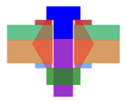
This is the overall strength of the joint, accounting for the male lug, the two female lugs, and the pin. The bearing areas between the pin and the lugs are shown in the figure to the right.
| Total Applied Force | Papp | |
| Overall Ultimate Load (Joint Strength) | Pult | |
| Factor of Safety | FS |
Female Lug
There is no female lug in this joint, so these results cannot be calculated.
Double Shear Joint Strength
There is no female lug in this joint, so these results cannot be calculated.
See full result details on the other tabs.
Component Properties
This section details the properties of the lug components.
Materials List
A list of all materials used in the joint is provided below:
| Elastic Modulus, E |
Percent Elongation, eL |
Ultimate Strain, εu |
Tensile Yield Strength, Sty |
Tensile Ultimate Strength, Stu |
Shear Yield Strength, Ssy |
Shear Ultimate Strength, Ssu |
Compressive Yield Strength, Scy |
Compressive Ultimate Strength, Scu |
|---|
NOTE: For ductile materials, compressive strength is approximately equal to tensile strength. For brittle materials, compressive strength is higher than tensile strength. In this analysis it is conservatively assumed that compressive strength is equal to tensile strength.
NOTE: The ultimate strain for a material is calculated based on the percent elongation, eL, the elastic modulus, E, and the ultimate tensile strength, Stu:
Applied Forces
| Pax | = | axial force | |
| Ptr | = | transverse force | |
| Papp | = | total applied force | |
| α | = | angle |
NOTE: There are 2 female lugs that share the applied load, so the load on a single female lug is half of that on the male lug.
Joint Properties
The joint consists of a single male lug, two female lugs, and a pin.
| g | = | gap between lugs (for bending arm) |
Pin Properties
| Material: |
| DP | = | diameter | |
| A | = | area | |
| S | = | section modulus | |
| kb.P | = | plastic bending coefficient |
Lug Dimensions
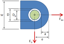
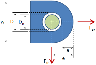
Lug dimensions are as shown in the figure below. Dimensions for the male lug and the female lugs (if applicable) are given in the following sections.

Male Lug Properties
| Material: | |
| Bushing Material: |
| w | = | width | |
| t2 | = | thickness | |
| D | = | hole diameter | |
| e | = | edge distance (hole center to edge of lug) | |
| a | = | distance (edge of hole to edge of lug) | |
| heff | = | effective edge distance |
Female Lug Properties
| Material | |
| Bushing Material: |
| w | = | width | |
| t1 | = | thickness | |
| D | = | hole diameter | |
| e | = | edge distance (hole center to edge of lug) | |
| a | = | distance (edge of hole to edge of lug) | |
| heff | = | effective edge distance |
Male Lug Results
Lug strengths in the axial and transverse directions are first calculated. The lug strength in the applied force direction (i.e. oblique loading) is then calculated, along with a Factor of Safety.
The table below gives a summary of the results. Full detailed calculations are provided in the following sections.
| Lug Strength for Pure Axial Loading | Pu.L.B | |
| Lug Strength for Pure Transverse Loading | Ptru.L.B | |
| Lug Strength for Oblique Loading | Pult | |
| Total Applied Force | Papp | |
| Factor of Safety | FS |
NOTE: There are 2 female lugs that share the applied load, so the load on a single female lug is half of that on the male lug.
Axial Loading
This section calculates the strength of the lug with a pure axial load applied.
Bearing Strength Under Axial Load
The ultimate bearing load accounts for bearing, shear-out, and hoop tension. Before calculating the ultimate bearing load, the axial load coefficient and bearing efficiency factor must be determined.
The axial load coefficient is determined from the figure below. This coefficient is only valid for D/t ≤ 5, which in this case. From the plot, the coefficient is:
| Kaxial = | () |
Reference Values
| D/t | = | |
| e/D | = | |
| D | = | |
| e | = | |
| t | = |
NOTE: This plot was generated based on the Air Force Manual, Figure 9-2.
The bearing efficiency factor is determined from the figure below. This coefficient is only valid for D/t > 5, which in this case. From the plot, the coefficient is:
| Kbear = | () |
Reference Values
| D/t | = | |
| e/D | = | |
| D | = | |
| e | = | |
| t | = |
NOTE: This plot was generated based on the Air Force Manual, Figure 9-3. The dotted lines in this figure were generated by finding the surrounding D/t curves, and the solid blue line was generated by interpolating between the surrounding curves.
Since D/t ≤ 5, the axial load coefficient is used:
| K = Kaxial = |
Since D/t > 5, the bearing efficiency factor is used:
| K = Kbear = |
The ultimate bearing load is calculated as:
|
|
Reference Values
| Sty | = | |
| Stu | = | |
| D | = | |
| a | = | |
| e | = | |
| t | = |
Bushing Bearing Strength Under Axial Load
The ultimate bushing load is calculated as:
| Pb.B = 1.304 Scy.B Dp t = |
NOTE: There was no bushing specified for this lug, so the bushing bearing strength was calculated using the compressive yield strength of the lug body material, .
Reference Values
Bushing:
| Scy.B | = | |
| DP | = | |
| t | = |
Net-Section Strength Under Axial Load
The net-section ultimate load accounts for tension failure across the net section. It depends on the net tension stress coefficient determined from the plot below:
| Kn = |
Reference Values
| D/w | = | |
| Sty / Stu | = | |
| Stu / (E⋅εu) | = |
NOTE: This plot was generated based on the Air Force Manual, Figure 9-4 (b), (c), and (d). The dotted lines in this figure were generated by interpolating within each of the three Air Force Manual figures based on the ratio Stu / (E⋅εu). The solid line was generated by interpolating between the figures based on the ratio Sty/Stu.
The net-section ultimate load is calculated as:
| Pnu.L = Kn · min(Stu , 1.304 Sty) · (w − D) · t = |
Reference Values
| Sty | = | |
| Stu | = | |
| D | = | |
| w | = | |
| t | = |
Design Strength Under Axial Load
The design ultimate load for an axially loaded lug is the minimum of the ultimate bearing load, the ultimate bushing load, and the ultimate net-section load:
| Pu.L.B = min( Pbru.L , Pu.B , Pnu.L ) = |
Reference Values
| Pbru.L | = | |
| Pu.B | = | |
| Pnu.L | = |
Transverse Loading
This section calculates the strength of the lug with a pure transverse load applied.
Lug Strength Under Transverse Load
The ultimate transverse load is dependent on the transverse ultimate and yield load coefficients determined from the plot below:
| Ktry = | transverse yield load coefficient | |
| Ktru = | transverse ultimate load coefficient |
Reference Values
| heff / D | = | |
| heff | = | |
| D | = |
NOTE: This plot was generated based on the Air Force Manual, Figure 9-8.
The ultimate transverse load is calculated as:
|
|
Reference Values
| Sty | = | |
| Stu | = | |
| D | = | |
| t | = |
Bushing Bearing Strength Under Transverse Load
The bearing strength for the bushing in a transversely loaded lug is the same as for an axially loaded lug:
| Ptru.B = Pu.B = |
Design Strength Under Transverse Load
The design ultimate load for a transversely loaded lug is the minimum of the ultimate lug load and the ultimate bushing load:
| Ptru.L.B = min( Ptru.L , Ptru.B ) = |
Reference Values
| Ptru.L | = | |
| Ptru.B | = |
Oblique Loading
This section calculates the strength of the lug under oblique loading (combined axial and transverse loading). Note that pure axial loading and pure transverse loading are special cases of oblique loading where only one load component is non-zero.
Applied Forces
The forces applied to the lug are:
| Pax | = | axial force | |
| Ptr | = | transverse force | |
| Papp | = | total applied force | |
| α | = | applied force angle |
NOTE: There are 2 female lugs that share the applied load, so the load on a single female lug is half of that on the male lug.
Lug Strength for Pure Axial and Transverse Loading
The lug strengths for pure loading in the axial and transverse directions are:
| Pu.L.B | = | lug strength for pure axial loading | |
| Ptru.L.B | = | lug strength for pure transverse loading |
Lug Strength for Oblique Loading
Lug strength for oblique loading is defined by an interaction equation that accounts for the interaction between the axial and transverse loading and strength. The interaction equation for lug strength is:
The failure locus of the plot to the left is defined by the interaction equation above. The axes of the plot are load ratios, which relate the applied load to the lug strength.
The current point on the plot is defined by the load ratios in the axial and transverse directions:
|
|
axial load ratio | |
|
|
transverse load ratio |
The load line in the plot extends from the origin through the current point and intersects with the failure locus. The critical point is the point at which the load line intersects the failure locus. This point gives the load ratios at which the lug fails.
|
|
ultimate axial load ratio | |
|
|
ultimate transverse load ratio |
The lug strength components for oblique loading in the applied direction are:
|
|
axial strength component | |
| Ptr.ult = Pax.ult · tan(α) = | transverse strength component |
Reference Values
| Pu.L.B | = | |
| Ptru.L.B | = | |
| α | = |
The lug strength for oblique loading in the applied direction is:
|
|
Reference Values
| Pax.ult | = | |
| Ptr.ult | = |
The Factor of Safety (FS) is:
|
|
|
Reference Values
| Pult | = | |
| Papp | = |
Female Lug Results
Lug strengths in the axial and transverse directions are first calculated. The lug strength in the applied force direction (i.e. oblique loading) is then calculated, along with a Factor of Safety.
The table below gives a summary of the results. Full detailed calculations are provided in the following sections.
| Lug Strength for Pure Axial Loading | Pu.L.B | |
| Lug Strength for Pure Transverse Loading | Ptru.L.B | |
| Lug Strength for Oblique Loading | Pult | |
| Total Applied Force | Papp | |
| Factor of Safety | FS |
NOTE: There are 2 female lugs that share the applied load, so the load on a single female lug is half of that on the male lug.
Axial Loading
This section calculates the strength of the lug with a pure axial load applied.
Bearing Strength Under Axial Load
The ultimate bearing load accounts for bearing, shear-out, and hoop tension. Before calculating the ultimate bearing load, the axial load coefficient and bearing efficiency factor must be determined.
The axial load coefficient is determined from the figure below. This coefficient is only valid for D/t ≤ 5, which in this case. From the plot, the coefficient is:
| Kaxial = | () |
Reference Values
| D/t | = | |
| e/D | = | |
| D | = | |
| e | = | |
| t | = |
NOTE: This plot was generated based on the Air Force Manual, Figure 9-2.
The bearing efficiency factor is determined from the figure below. This coefficient is only valid for D/t > 5, which in this case. From the plot, the coefficient is:
| Kbear = | () |
Reference Values
| D/t | = | |
| e/D | = | |
| D | = | |
| e | = | |
| t | = |
NOTE: This plot was generated based on the Air Force Manual, Figure 9-3. The dotted lines in this figure were generated by finding the surrounding D/t curves, and the solid blue line was generated by interpolating between the surrounding curves.
Since D/t ≤ 5, the axial load coefficient is used:
| K = Kaxial = |
Since D/t > 5, the bearing efficiency factor is used:
| K = Kbear = |
The ultimate bearing load is calculated as:
|
|
Reference Values
| Sty | = | |
| Stu | = | |
| D | = | |
| a | = | |
| e | = | |
| t | = |
Bushing Bearing Strength Under Axial Load
The ultimate bushing load is calculated as:
| Pb.B = 1.304 Scy.B Dp t = |
NOTE: There was no bushing specified for this lug, so the bushing bearing strength was calculated using the compressive yield strength of the lug body material, .
Reference Values
Bushing:
| Scy.B | = | |
| DP | = | |
| t | = |
Net-Section Strength Under Axial Load
The net-section ultimate load accounts for tension failure across the net section. It depends on the net tension stress coefficient determined from the plot below:
| Kn = |
Reference Values
| D/w | = | |
| Sty / Stu | = | |
| Stu / (E⋅εu) | = |
NOTE: This plot was generated based on the Air Force Manual, Figure 9-4 (b), (c), and (d). The dotted lines in this figure were generated by interpolating within each of the three Air Force Manual figures based on the ratio Stu / (E⋅εu). The solid line was generated by interpolating between the figures based on the ratio Sty/Stu.
The net-section ultimate load is calculated as:
| Pnu.L = Kn · min(Stu , 1.304 Sty) · (w − D) · t = |
Reference Values
| Sty | = | |
| Stu | = | |
| D | = | |
| w | = | |
| t | = |
Design Strength Under Axial Load
The design ultimate load for an axially loaded lug is the minimum of the ultimate bearing load, the ultimate bushing load, and the ultimate net-section load:
| Pu.L.B = min( Pbru.L , Pu.B , Pnu.L ) = |
Reference Values
| Pbru.L | = | |
| Pu.B | = | |
| Pnu.L | = |
Transverse Loading
This section calculates the strength of the lug with a pure transverse load applied.
Lug Strength Under Transverse Load
The ultimate transverse load is dependent on the transverse ultimate and yield load coefficients determined from the plot below:
| Ktry = | transverse yield load coefficient | |
| Ktru = | transverse ultimate load coefficient |
Reference Values
| heff / D | = | |
| heff | = | |
| D | = |
NOTE: This plot was generated based on the Air Force Manual, Figure 9-8.
The ultimate transverse load is calculated as:
|
|
Reference Values
| Sty | = | |
| Stu | = | |
| D | = | |
| t | = |
Bushing Bearing Strength Under Transverse Load
The bearing strength for the bushing in a transversely loaded lug is the same as for an axially loaded lug:
| Ptru.B = Pu.B = |
Design Strength Under Transverse Load
The design ultimate load for a transversely loaded lug is the minimum of the ultimate lug load and the ultimate bushing load:
| Ptru.L.B = min( Ptru.L , Ptru.B ) = |
Reference Values
| Ptru.L | = | |
| Ptru.B | = |
Oblique Loading
This section calculates the strength of the lug under oblique loading (combined axial and transverse loading). Note that pure axial loading and pure transverse loading are special cases of oblique loading where only one load component is non-zero.
Applied Forces
The forces applied to the lug are:
| Pax | = | axial force | |
| Ptr | = | transverse force | |
| Papp | = | total applied force | |
| α | = | applied force angle |
NOTE: There are 2 female lugs that share the applied load, so the load on a single female lug is half of that on the male lug.
Lug Strength for Pure Axial and Transverse Loading
The lug strengths for pure loading in the axial and transverse directions are:
| Pu.L.B | = | lug strength for pure axial loading | |
| Ptru.L.B | = | lug strength for pure transverse loading |
Lug Strength for Oblique Loading
Lug strength for oblique loading is defined by an interaction equation that accounts for the interaction between the axial and transverse loading and strength. The interaction equation for lug strength is:
The failure locus of the plot to the left is defined by the interaction equation above. The axes of the plot are load ratios, which relate the applied load to the lug strength.
The current point on the plot is defined by the load ratios in the axial and transverse directions:
|
|
axial load ratio | |
|
|
transverse load ratio |
The load line in the plot extends from the origin through the current point and intersects with the failure locus. The critical point is the point at which the load line intersects the failure locus. This point gives the load ratios at which the lug fails.
|
|
ultimate axial load ratio | |
|
|
ultimate transverse load ratio |
The lug strength components for oblique loading in the applied direction are:
|
|
axial strength component | |
| Ptr.ult = Pax.ult · tan(α) = | transverse strength component |
Reference Values
| Pu.L.B | = | |
| Ptru.L.B | = | |
| α | = |
The lug strength for oblique loading in the applied direction is:
|
|
Reference Values
| Pax.ult | = | |
| Ptr.ult | = |
The Factor of Safety (FS) is:
|
|
|
Reference Values
| Pult | = | |
| Papp | = |
There is no female lug in this joint, so these results cannot be calculated.
Double Shear Joint Strength
In this section, the double shear joint strength is calculated which gives the overall strength of the joint accounting for the interactions between the lugs and the pin. The table below gives a summary of the results. Full detailed calculations are provided in the following sections.
| Overall Ultimate Load (Joint Strength) | Pult | |
| Total Applied Force | Papp | |
| Factor of Safety | FS |
Nominal Joint Strength
The strengths of the male and female lugs, calculated in the previous sections, are:
| Pult.M = | male lug strength | |
| Pult.F = | female lug strength |
The nominal joint strength, ignoring the effects of pin bending, is:
| Pu.J.nom = min( 2·Pult.F , Pult.M ) = | nominal joint strength |
Nominal Pin Strength
The nominal shear strength and bending strength of the pin are:
|
|
pin ultimate shear load | |
|
|
pin ultimate bending load |
Reference Values
| Stu.P | = | |
| Ssu.P | = | |
| DP | = | |
| kb.P | = | |
| t1 | = | |
| t2 | = | |
| g | = |
Pin Strong or Weak in Bending?
For the pin to be considered strong in bending, the pin ultimate bending load Pub.P must be greater than either the pin ultimate shear load Pus.P or the nominal ultimate joint load Pu.J.nom. One of the conditions below must hold true for the pin to be strong in bending:
| Pub.P ≥ Pu.J.nom | or | Pub.P ≥ Pus.P |
At least one of the conditions above does hold true, so the pin is strong in bending.
The conditions above do not hold true, so the pin is weak in bending.
Reference Values
| Pub.P | = | |
| Pus.P | = | |
| Pu.J.nom | = |
Strong Pin
For a strong pin, the the pin ultimate bending load is calculated assuming that the load distributes evenly over the full width of the lugs (i.e. same as the nominal value):
|
|
pin ultimate bending load |
Reference Values
| Stu.P | = | |
| DP | = | |
| kb.P | = | |
| t1 | = | |
| t2 | = | |
| g | = |
For a strong pin, the pin bending does not affect the joint strength and the ultimate joint load is equal to the nominal ultimate joint load:
| Pu.J = Pu.J.nom = | ultimate joint load |
Weak Pin
For a weak pin, the load will not be distributed evenly over the lug widths and will instead concentrate toward the outer portions of the lugs at the shear planes. A "balanced design" is found that accounts for the reduced bearing areas between the pin and the lugs. The bearing widths for the male and female lugs are calculated such that the male lug strength, the female lug strength, and the pin bending strength are all equal.
The bearing widths for the male and female lugs are the widths over which the pin loads are supported:
| b1 = | bearing width over female lug | |
| b2 = | bearing width over male lug |
Reference Values
| t1 | = | |
| t2 | = |
Because the bearing widths are smaller than the full lug thicknesses, the moment arm is reduced and the pin ultimate bending load is increased:
|
|
pin ultimate bending load |
Reference Values
| Stu.P | = | |
| DP | = | |
| kb.P | = | |
| g | = |
In the balanced design, the ultimate joint load is equal to the pin ultimate bending load:
| Pu.J = Pub.P = | ultimate joint load |
Note that the same joint strength would be achieved if the width of each female lug was reduced to b1 = and the width of the male lug reduced to 2b2 = .
Overall Ultimate Load
The overall ultimate load accounts for both the ultimate joint load and the ultimate pin shear load:
| Pult = min( Pu.J , Pus.P ) = | overall ultimate load |
Reference Values
| Pu.J | = | |
| Pus.P | = |
The overall ultimate load must be compared to the applied force to determine the factor of safety:
| Papp = | total applied force |
The Factor of Safety (FS) is:
|
|
|
Reference Values
| Pult | = | |
| Papp | = |
There is no female lug in this joint, so these results cannot be calculated.
Download Report
Save a formatted Word document to your computer detailing the inputs and results of the analysis.
Download Inputs File
Save all input data to a file. You can later upload this file to pick back up where you left off.
Need More Functionality?
Sign up for an account to receive full access to all calculators and other content. The subscription types are described below, along with the benefits of each.
- Price
- Access to Calculators
- Login
- Create Materials
- Create Cross Sections
- Save Files
- Reporting
- Free
-
LimitedLimited Access to Calculators
-
NoneNo Login
-
Pre-defined Materials
-
Pre-defined Cross Sections
-
No Saved Files
-
No Reporting
- Learn More »
-
USD $9.99 /month USD $99.99 /year -
FullFull Access to Calculators
-
IndividualIndividual Login
-
Create Materials
-
Create Cross Sections
-
Unlimited Saved Files
-
Unlimited Reporting
- Learn More »
- Sign Up Now
-
USD $29.99 /month USD $299.99 /year -
FullFull Access to Calculators
-
Floating LicensesFloating Licenses
-
Create Materials
-
Create Cross Sections
-
Unlimited Saved Files
-
Unlimited Reporting
- Learn More »
- Sign Up Now
-
Bulk pricing (≥20 educational licenses)
-
FullFull Access to Calculators
-
Floating LicensesFloating Licenses
-
Create Materials
-
Create Cross Sections
-
Unlimited Saved Files
-
Unlimited Reporting
- Learn More »
- Sign Up Now
Solving, please wait...

Looking for Other Calculators?
Here are just a few of the calculators that we have to offer:
Feedback
Do you have any comments or suggestions? We would love to hear them!
