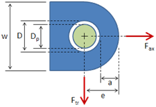
Lug Analysis Instructions
This page provides instructions on the use of the Lug Analysis calculator.
Reference and Validation
Reference: A general description of the theory and the methodology used can be found here.
Validation: This tool has been validated against the known solutions to numerous example problems. Documentation of the validation can be found here.
Inputs
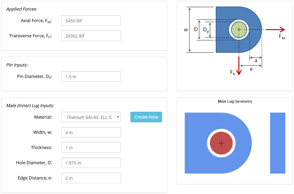
In the inputs section, all of the relevant details pertaining to the analysis are entered. At a minimum, these inputs include:
- Applied forces
- Pin diameter
- Male lug material & dimensions
An analysis can be run specifying only the inputs above. In this case, only the male lug strength results will be calculated. The input form pertaining to the minimum set of inputs is shown below:
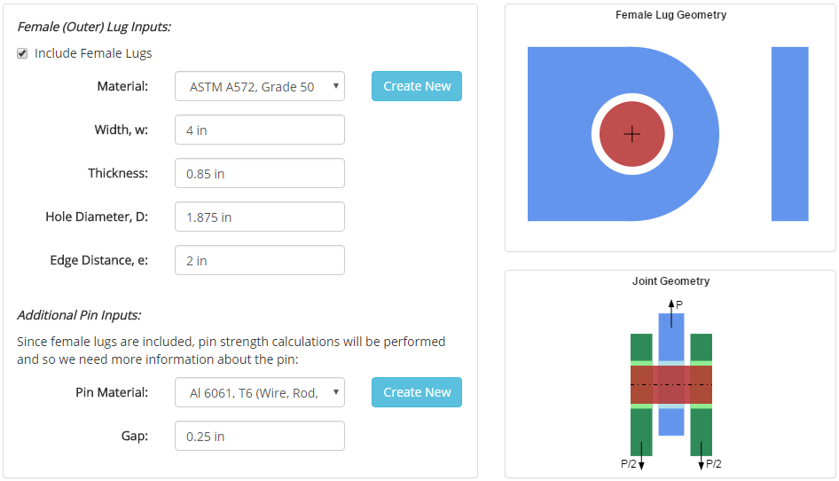
The joint can optionally include an outer set of female lugs. If included, results will also be calculated for the two female lugs and for double shear joint strength. Additional inputs required for the female lug inputs include:
- Female lug material & dimensions
- Pin material
- Gap between male lug and female lug
Materials and cross sections are specified in separate sections of this site, and once they are specified they will show up in the drop-down menus on the input form.
Once all of the inputs are entered, hitting the 'Submit' button will solve the analysis, and the results will be displayed.
Results
After the analysis is solved, results are displayed in multiple tabs. Each results tab is discussed in the following sections.
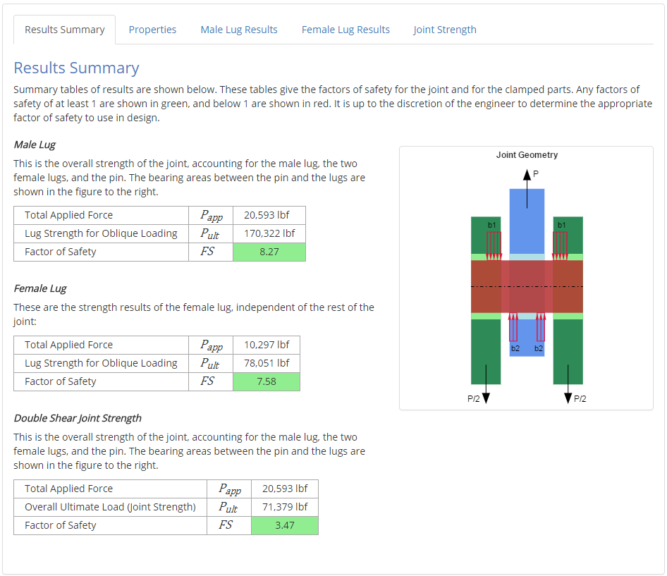
Results Summary
A summary of the results is provided to give a high-level overview of the factors of safety for the male lug and, if relevant, the female lugs and the double shear joint strength.
Properties
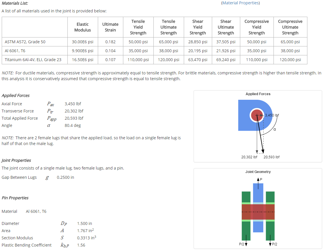
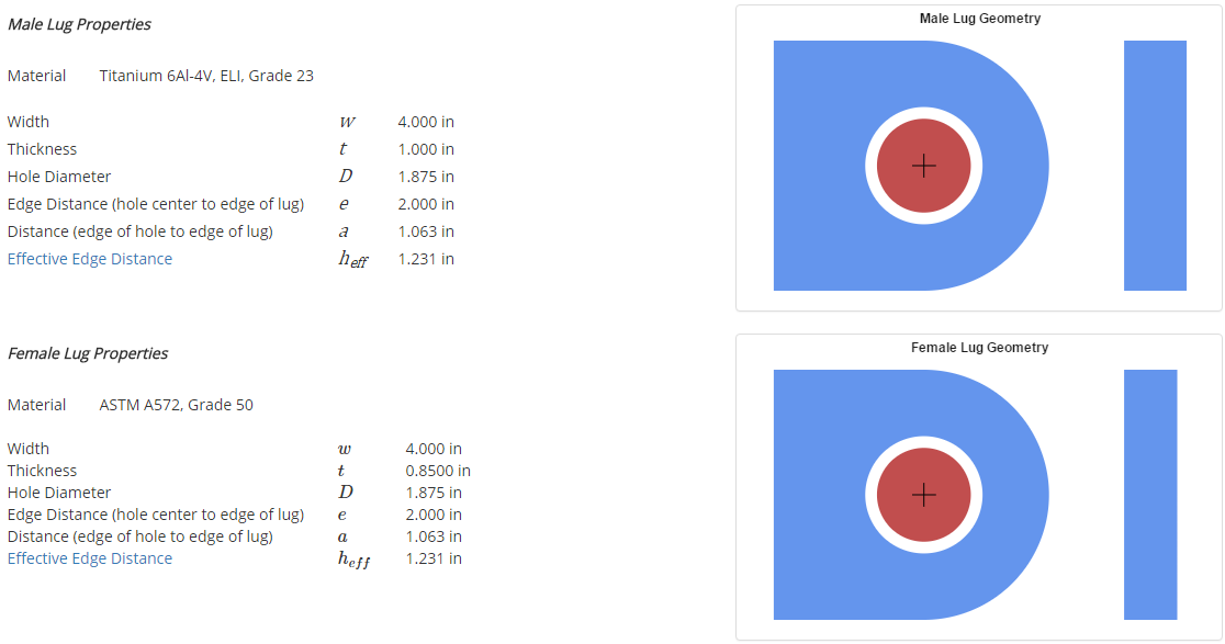
This tab outlines the relevant properties of the components in the lug joint. The major properties of interest include:
- Material properties
- Applied forces
- Pin properties (diameter, and material if relevant)
- Male lug properties (material & dimensions)
- Female lug properties, if relevant (material & dimensions)
The way in which these properties are used in the analysis is described in more detail in the Reference section.
Male & Female Lug Results
The results sections for the male lug and the female lug are long, but the highlights are provided here.
Axial Loading
Lug strength for a pure axial applied load is calculated first. Of primary interest is the determination of the axial load coefficient, the bearing efficiency factor, and the net tension stress coefficient for the current lug geometry and material.
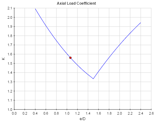
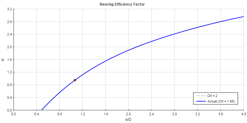
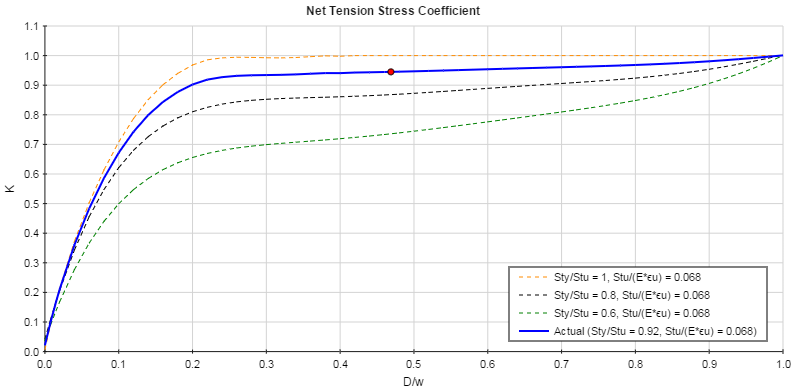
The coefficients determined from the plots combined with the lug geometry and material properties allow for the calculation of the lug axial strength.
Transverse Loading
Lug strength for a pure transverse applied load is then calculated. Of primary interest is the determination of the transverse yield load coefficient and the transverse ultimate load coefficient for the current lug geometry.
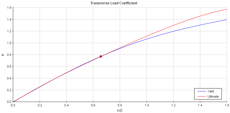
The coefficients determined from the plots combined with the lug geometry and material properties allow for the calculation of the lug axial strength.
Oblique Loading
The axial and transverse strengths are used to calculate the lug strength for oblique loading (combined axial and transverse loading). An allowable load curve is generated to determine the lug strength components for loading in the applied direction.
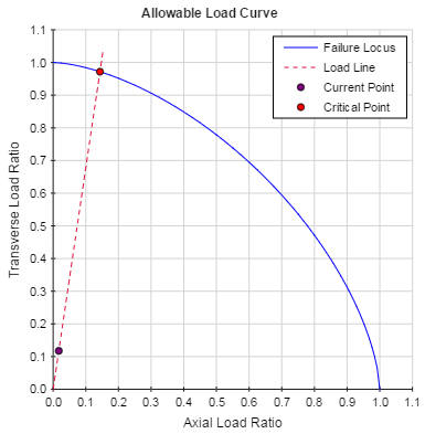
The lug strength for oblique loading in the applied direction can then be calculated along with the factor of safety:

Double Shear Joint Strength
If female lug inputs are specified, the double shear joint strength is calculated which gives the overall strength of the joint accounting for the interactions between the lugs and the pin. If the pin is weak in bending, then a balanced design is found in which the male lug strength, the female lug strength, and the pin bending strength are all equal.
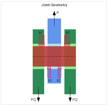
An overall ultimate joint load is calculated along with a factor of safety:

