Beam Analysis Quick Reference (Formula Sheet)
This page provides a quick reference formula sheet for the calculation of stresses and deflections in beams.
Shear Force and Bending Moment
To find the shear force and bending moment over the length of a beam, first solve for the external reactions at the boundary conditions. Then take section cuts along the length of the beam and solve for the reactions at each section cut, as shown below. The side of the section cut that is chosen will not affect the results.
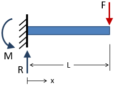
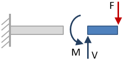
Sign Convention
| Shear | Bending Moment |
|---|---|
| Positive shear causes clockwise rotation of the selected beam section, negative shear causes counter-clockwise rotation. | Positive moment compresses the top of the beam and elongates the bottom (i.e. it makes the beam "smile"). Negative moment makes the beam "frown". |

Shear and Moment Diagrams
The shear and bending moment throughout a beam are commonly expressed using shear and moment diagrams. An example of a shear-moment diagram is shown here.
General rules for drawing shear-moment diagrams are given in the table below.
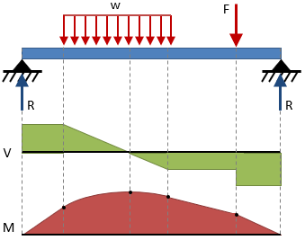
| Shear Diagram | Moment Diagram |
|---|---|
|
|
Bending Stresses in Beams
The bending stress in a beam is zero at the neutral axis and increases linearly with distance from the neutral axis according to the flexure formula:
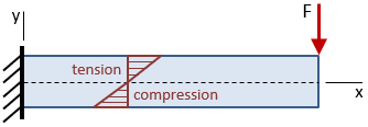
| Flexure formula (bending stress vs. distance from neutral axis): |
|
| Max bending stress occurs at extreme fiber: |
|
where M is the moment at the location along the beam length, taken from the moment diagram.
Bending stress in an asymmetric beam:
|
|
|
|
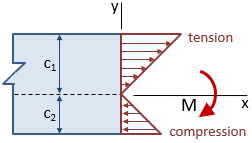
The section modulus, S, characterizes bending resistance of a cross section in a single term:
Max bending stress in a beam:
Section modulus & bending stress for common shapes:
| Rectangular: |
|
|
|
| Circular: |
|
|
|
Shear Stresses in Beams
Average shear stress in beam at a specific location along the length of the beam:
where V is the shear stress at the location, taken from the shear diagram.
Shear stress at distance y1 from centroid of cross section:
Q is the first moment of the area of the cross section:

Max shear stress for common cross sections:
Beam Deflection Tables
Tables of equations for the deflection, slope, shear, and moment along straight beams for different end conditions and loadings can be found on this page.
Check out our beam calculator based on the methodology described here.
- Calculates stresses and deflections in straight beams
- Builds shear and moment diagrams
- Can specify any configuration of constraints, concentrated forces, and distributed forces
References
- Budynas-Nisbett, "Shigley's Mechanical Engineering Design," 8th Ed.
- Gere, James M., "Mechanics of Materials," 6th Ed.
- Lindeburg, Michael R., "Mechanical Engineering Reference Manual for the PE Exam," 13th Ed.
- "Stress Analysis Manual," Air Force Flight Dynamics Laboratory, October 1986.
