NOTE: This page relies on JavaScript to format equations for proper display. Please enable JavaScript.
The tables below give equations for the deflection, slope, shear, and moment along straight beams for different end conditions and loadings. You can find comprehensive tables in references such as Gere , Lindeburg , and Shigley . However, the tables below cover most of the common cases.
For information on beam deflection, see our reference on stresses and deflections in beams .
Cantilever Beams
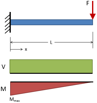
Cantilever, End Load
@ x = L
@ x = L
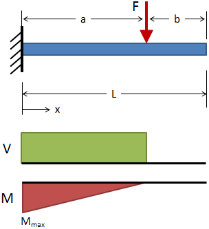
Cantilever, Intermediate Load
( 0 ≤ x ≤ a )
( a ≤ x ≤ L )
@ x = L
( 0 ≤ x ≤ a )
( a ≤ x ≤ L )
V = +F ( 0 ≤ x ≤ a )
V = 0 ( a ≤ x ≤ L )
M = −F (a − x) ( 0 ≤ x ≤ a )
M = 0 ( a ≤ x ≤ L )
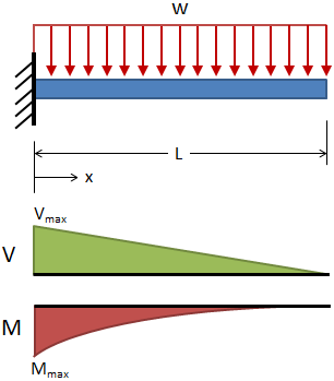
Cantilever, Uniform Distributed Load
@ x = L
@ x = L
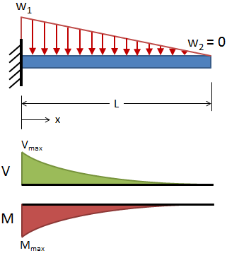
Cantilever, Triangular Distributed Load
@ x = L
@ x = L
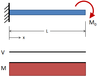
Cantilever, End Moment
@ x = L
@ x = L
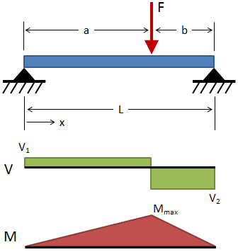
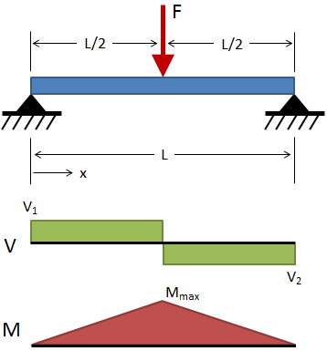
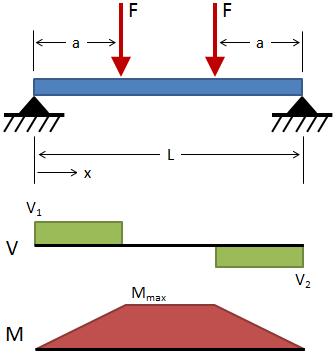
Simply Supported Beams
Fixed-Fixed Beams
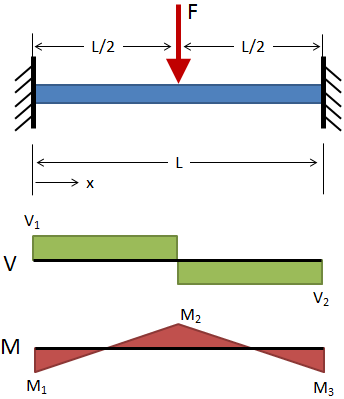
Fixed-Fixed, Center Load
( 0 ≤ x ≤ L/2 )
@ x = L/2
V1 = +F / 2 ( 0 ≤ x ≤ L/2 )
V2 = −F / 2 ( L/2 ≤ x ≤ L )
M = F (4x − L) / 8 ( 0 ≤ x ≤ L/2 )
M1 = M3 = −FL / 8 @ x = 0 & x = L
M2 = +FL / 8 @ x = L/2
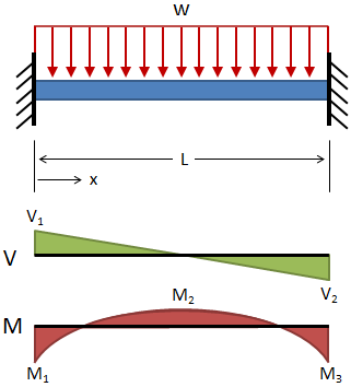
Fixed-Fixed, Uniform Distributed Load
@ x = L/2
V1 = +wL / 2 @ x = 0
V2 = −wL / 2 @ x = L
M = w (6Lx − 6x2 − L2 ) / 12
M1 = M3 = −wL2 / 12 @ x = 0 & x = L
M2 = wL2 / 24 @ x = L/2
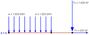
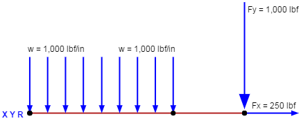
Check out our beam calculator based on the methodology described here.
Calculates stresses and deflections in straight beams
Builds shear and moment diagrams
Can specify any configuration of constraints, concentrated forces, and distributed forces
References
Budynas-Nisbett, "Shigley's Mechanical Engineering Design," 8th Ed.
Gere, James M., "Mechanics of Materials," 6th Ed.
Lindeburg, Michael R., "Mechanical Engineering Reference Manual for the PE Exam," 13th Ed.
