Stress Intensity Factor Solutions
This page provides stress intensity factor solutions for common cases.
Contents
Center Through Crack in Plate
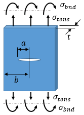
| Stress intensity: |
|
| Geometry factor, tension: |
|
| Geometry factor, bending: | Yb = Yt / 2 |
Definitions:
| σt | tensile stress |
| σb | bending stress |
| a | crack half-length |
| b | plate half-width |
References:
- AFRL-VA-WP-TR-2003-3002, "USAF Damage Tolerant Design Handbook: Guidelines for the Analysis and Design of Damage Tolerant Aircraft Structures," 2002
- API 579-1 / ASME FFS-1, "Fitness-For-Service," The American Petroleum Institute and The American Society of Mechanical Engineers, 2007
Single Edge Through Crack in Plate
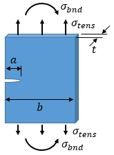
| Stress intensity: |
|
| Geometry factor, tension: |
|
| Geometry factor, bending: |
|
| Dimension ratio: | α = a / b |
Definitions:
| σt | tensile stress |
| σb | bending stress |
| a | crack length |
| b | plate width |
References:
Elliptical Surface Crack in Plate
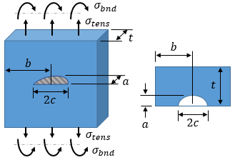
| Stress intensity: |
|
| Geometry factor, tension: |
|
| Geometry factor, bending: | Yb = H·Yt |
|
|
|
| H = H1 + (H2 − H1)(sin ϕ)p | |
| ϕ = 0° at c-tip, ϕ = 90° at a-tip (full depth of crack) |
| a ≤ c | a > c |
|---|---|
|
|
|
|
|
|
|
|
|
|
|
|
|
|
|
|
|
|
|
|
|
|
|
|
|
|
|
|
|
|
|
|
|
| --- |
|
|
|
|
| --- |
|
Definitions:
| σt | tensile stress |
| σb | bending stress |
| a | crack depth |
| c | crack half-length |
| b | plate half-width |
| t | plate thickness |
References:
Corner Surface Crack in Plate
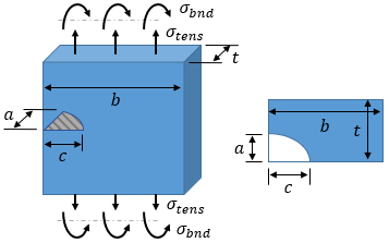
| Stress intensity: |
|
| Geometry factor, tension: |
|
| Geometry factor, bending: |
|
|
|
|
| H = H1 + (H2 − H1)(sin ϕ)p | |
| ϕ = 0° at c-tip, ϕ = 90° at a-tip |
| a ≤ c | a > c |
|---|---|
|
|
|
|
|
|
|
|
|
|
|
|
|
|
|
|
|
|
|
|
|
|
|
|
|
|
|
|
|
|
|
|
|
|
|
|
| --- |
|
|
|
|
| --- |
|
Definitions:
| σt | tensile stress |
| σb | bending stress |
| a | crack depth |
| c | crack length |
| b | plate width |
References:
Thumbnail Crack in Solid Cylinder
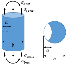
| Stress intensity: |
|
| Geometry factor, tension: |
|
| Geometry factor, bending: |
|
|
|
|
|
|
|
|
|
Definitions:
| σt | tensile stress |
| σb | bending stress |
| a | crack depth |
| b | cylinder diameter |
References:
- AFRL-VA-WP-TR-2003-3002, "USAF Damage Tolerant Design Handbook: Guidelines for the Analysis and Design of Damage Tolerant Aircraft Structures," 2002
