Bolted Joint Analysis
The Bolted Joint Analysis calculator allows for stress analysis of a bolted joint, accounting for preload, applied axial load, and applied shear load. See the instructions within the documentation for more details on performing this analysis. See the reference section for details on the methodology and the equations used.
Inputs
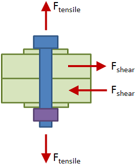
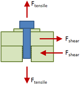
Input the details for the bolted joint, then click the "Calculate Results" button:
Display Units
Display results in:
Results
The results of the bolted joint analysis are detailed below. Refer to the bolted joint analysis reference section for details on how these results were derived.
Results Summary
Summary tables of results are shown below. These tables give the factors of safety for the joint and for the clamped parts. Any factors of safety of at least 1 are shown in green, and below 1 are shown in red. It is up to the discretion of the engineer to determine the appropriate factor of safety to use in design.
Joint Summary
The table below summarizes the factors of safety for the joint corresponding to the nominal, maximum, and minimum bolt load (the bolt load varies based on preload uncertainty and relaxation).
| FSseparation | FSbolt yield | FSthread shear bolt | FSthd shear internal | |
|---|---|---|---|---|
| Nominal: | ||||
| Max Bolt Load: | --- | --- | ||
| Min Bolt Load: | --- | --- |
Clamped Parts Summary
The table below summarizes the factors of safety for each clamped part in the grip.
| FSpull thru | FSpin bearing | FSbearing, top surface | FSbearing, bot surface |
|---|
See full result details on the other tabs.
Joint Properties
This section details the properties of the bolted joint components.
Inputs
| Joint Type | Tensile Force |
Shear Force |
Bolt Material | Thread Size |
Preload % |
Torque Coefficient |
Preload Uncertainty |
Preload Relaxation |
|---|---|---|---|---|---|---|---|---|
Materials List
| Elastic Modulus | Tensile Yield Strength | Shear Yield Strength | Bearing Yield Strength |
|---|
Bolt Properties
| Material: | |
| Thread Size: |
| dnom | = | nominal diameter | |
| TPI | = | threads per inch | |
| P | = | pitch | |
| dm | = | minor diameter | |
| dp | = | pitch diameter | |
| At | = | tensile stress area | |
| As | = | minor (shear) area | |
| L | = | length | |
| Lt | = | thread length | |
| dhead | = | head diameter |
Nut Properties
| Material: |
| hnut | = | nut height | |
| wnut | = | width across flats |
Clamped Parts List
| Grip Thk | Hole Dia | Width | Material |
|---|
Bolt Length Calculation
| Grip: | Grip length | |
| Threaded Member: | Additional length to protrude through threaded member. | |
| 2 threads: | 2 threads at the end to ensure full engagement | |
| Total: | Length of the bolt before rounding up to the preferred size |
The bolt length was rounded up to the preferred size of .
Joint Stiffness
Bolt Stiffness
The individual stiffnesses of the shank and the threads in the grip are calculated as:
| Stiffness of shank: |
|
|
| Stiffness of threads in grip: |
|
Reference Values
| Anom | = | |
| At | = | |
| E | = | |
| Lshank | = | |
| Lthd.g | = |
The bolt stiffness is calculated considering that the shank and threads in the grip act as springs in series:
|
|
Grip Stiffness
The stiffness of each part in the grip is calculated based on a simplified pressure-cone method, as described here. The table below shows the stiffness for each part:
| Grip Thk | Hole Dia | Elastic Modulus | Stiffness |
|---|
The grip stiffness is calculated considering that the parts in the grip act as springs in series:
|
|
Joint Constant
The joint constant is the stiffness of the bolt relative to the total joint stiffness:
|
|
Joint Installation
This section details the parameters relevant to installation of the joint. A summary of the installation parameters is given in the table below:
| Preload (% Yield) |
Preload Force | Torque Coefficient, KT |
Install Torque |
|---|---|---|---|
Reference Values
| %yld | = | |
| Sty | = | |
| At | = |
Reference Values
| KT | = | |
| dnom | = | |
| FPL | = |
Bolt Forces & Stresses
This section details the force and stress analysis on the bolt itself.
Preload Force
The nominal preload force is calculated as:
| FPL.nom = %yld · Sty At = |
Warning: The preload in this joint is unusually low. It is recommended that the preload %yld be within the range of 64% - 77%. This ensures that the clamped parts always remain in contact and in compression. A higher preload also allows you to get more utility out of the bolted joint (up to a point), since a higher preload increases the force necessary to separate the joint. See this preload reference for more details.
Reference Values
| %yld | = | |
| Sty | = | |
| At | = |
Due to preload uncertainty, the actual preload applied to the bolt may be more or less than the nominal value. Due to preload relaxation, there will be some loss in the preload after the joint is installed.
The maximum value of preload accounts for the preload uncertainty, and is calculated as:
| FPL.max = (1 + %uncrt ) · FPL.nom = |
The minimum value of preload accounts for the preload uncertainty as well as relaxation, and is calculated as:
| FPL.min = (1 − %uncrt − %relax ) · FPL.nom = |
Reference Values
| FPL.nom | = | |
| %uncrt | = | |
| %relax | = |
The table below summarizes the preload values. The nominal value is the design target, and the min and max values account for preload uncertainty and relaxation.
| Nominal | Minimum | Maximum | |
|---|---|---|---|
| Preload Force: |
Bolt Load Diagram
The Bolt Load Diagram below shows the tensile load on the bolt as a function of applied tensile load on the joint. The dark blue line gives the nominal bolt load, and the light blue lines account for preload uncertainty and relaxation. The knee in the curve shows the point at which the joint separates.
Before joint separation, only a portion of the applied load is carried by the bolt, and the other portion acts to relieve compression in the clamped parts. The bolt load line in this region has a constant slope equal to the joint constant. After separation, all applied load is taken by the bolt and so the bolt load line has a slope of 1.
Joint Constant
The value of the joint constant is determined by calculating the stiffness of the bolt, kbolt, and the stiffness of the clamped parts in the grip, kgrip. The once the stiffnesses are known, the joint constant is calculated as:
The joint constant for this joint was calculated in the Joint Properties tab as:
| Joint Constant, C |
|---|
Joint Separation
The separation force is the force that will result in separation of the joint. A summary of the separation force values and their corresponding factors of safety is given in the table below. The nominal and minimum values in the table correspond to the nominal preload and the minimum preload, respectively.
| Separation Force | FSsep | |
|---|---|---|
| Nominal: | ||
| Minimum: | ||
| Maximum: |
The minimum separation force dictates the adequacy of the joint and is calculated below:
|
|
Reference Values
| FPL.min | = | |
| C | = |
The factor of safety on joint separation is calculated as the ratio of the separation force to the applied tensile load:
|
|
Reference Values
| Fsep.min | = | |
| Ft.app | = |
Tensile Force on Bolt
The total (combined) tensile force on the bolt is the sum of the tension due to preload and the tension due to the applied load. The values of these tension components are dependent on whether the joint has separated. Refer to the Bolt Load Diagram above for a visual indication of joint separation. The combined tensile force on the bolt is calculated as:
The combined tensile forces on the bolt corresponding to the nominal, minimum, and maximum values of preload are given in the table below:
| Separated? | Combined Tensile Force | |||
|---|---|---|---|---|
| Nominal: |
|
|||
| Minimum: |
|
|||
| Maximum: |
|
Reference Values
| FPL.nom | = | |
| FPL.min | = | |
| FPL.max | = | |
| C | = | |
| Ft.app | = |
The table below summarizes the tensile force components on the bolt. The nominal, minimum, and maximum values in the table correspond to the nominal, minimum, and maximum values of preload, respectively. Note that if the joint has not separated, the bolt will only take a portion of the applied tensile load.
| Separated? | Preload, Fb.PL |
Applied Load, Fb.t.app |
Total (Combined), Fb.t |
|
|---|---|---|---|---|
| Nominal: | ||||
| Minimum: | ||||
| Maximum: |
Shear Force on Bolt
The shear force on the bolt is equal to the shear load applied to the joint:
| Fb.s = Fs.app = |
Reference Values
| Fs.app | = |
Bolt Stresses
The stresses in the bolt are calculated per the equations in the table below:
| Preload Stress | Tensile Stress | Shear Stress | Von Mises Stress |
|---|---|---|---|
|
|
|
|
|
where Fb.PL is the tensile force on the bolt due to preload, Fb.t.app is the tensile force on the bolt due to applied tensile load, Fb.s is the shear force on the bolt, At is the tensile stress area, and As is the minor (shear) area. The value n in the equation for von Mises stress is the load factor. The load factor is related to the factor of safety, with the difference being that it is a factor that is applied to the loads or stresses to ensure that the bolt stress remains below the allowable stress.
The stresses at the maximum bolt preload determine the adequacy of the joint. The preload stress at the maximum preload value is:
|
|
Reference Values
| Fb.PL.max | = | |
| At | = |
The tensile stress due to applied tensile load at the maximum preload value is:
|
|
Reference Values
| Fb.t.app.max | = | |
| At | = |
The shear stress due to applied shear load is:
|
|
Reference Values
| Fb.s | = | |
| As | = |
The von Mises stress at the maximum preload value, considering a load factor of 1, is:
|
|
Reference Values
| σPL.max | = | |
| σt.max | = | |
| τsh | = | |
| n | = | 1 |
The factor of safety when considering bolt stress is the value of the load factor, n, at which the von Mises stress equals the allowable stress (the bolt yield stress in this case). At the maximum preload value, the factor of safety is:
| FS = |
Reference Values
| Sty | = |
The bolt stresses are summarized in the table below summarizes the tensile force components on the bolt. The nominal, minimum, and maximum values in the table correspond to the nominal, minimum, and maximum values of preload, respectively.
| Preload Stress | Tensile Stress (App) | Shear Stress | Von Mises Stress | FSyld | |
|---|---|---|---|---|---|
| Nominal: | |||||
| Minimum: | |||||
| Maximum: |
Thread Shear Results
Thread shear is considered for both the bolt (external) threads and the internal threads.
Since this joint includes a bolt with a nut, the length of thread engagement is simply the nut height:
| LE = hnut = |
Reference Values
| hnut | = |
Since this is a tapped joint, the length of thread engagement is the minimum of the tapped part thickness, tp, or the bolt nominal diameter, dnom:
| LE = min(tp , dnom) = |
Reference Values
| tp | = | |
| dnom | = |
External Thread Shear
The thread shear area for the external thread is calculated by:
|
|
Reference Values
| dp.ext | = | |
| LE | = |
The shear stress in the external threads in the nominal case (where preload equals the nominal value) is:
|
|
Reference Values
| Fb.t | = | |
| Ats.ext | = |
The factor of safety on external thread shear with respect to the shear yield strength, Ssy, of the thread material is:
|
|
Reference Values
| Ssy | = | |
| τts.ext | = |
Internal Thread Shear
The thread shear area for the internal thread is calculated by:
|
|
Reference Values
| dp.int | = | |
| LE | = |
The shear stress in the internal threads in the nominal case (where preload equals the nominal value) is:
|
|
Reference Values
| Fb.t | = | |
| Ats.int | = |
The factor of safety on internal thread shear with respect to the shear yield strength, Ssy, of the thread material is:
|
|
Reference Values
| Ssy | = | |
| τts.int | = |
Thread Shear Summary
The table below summarizes the thread shear results:
| Thread Shear Force |
Thread Shear Area |
Thread Shear Stress |
Thread Shear Allowable |
FSthd shear | |
|---|---|---|---|---|---|
| External (Bolt) Thread | |||||
| Internal Thread |
Clamped Parts Results
Failure of the clamped parts must be investigated when analyzing a bolted joint. There are several principal failure mechanisms for the clamped parts which are described below.
Pull Through
The tensile force applied to the joint will act to pull the parts through one another. The relevant equations for analyzing pull through are:
| Area | Stress | Factor of Safety |
|---|---|---|
| Apt = πdotp |
|
|
In the table above, do is the outer diameter of the part pulling through, tp is the thickness of the part being considered, Ft.app is the applied tensile force, and Ssy is the shear yield strength of the material for the part being considered.
The table below summarizes the pull through results. The part listed in the "Pull Thru Part" column is acting to pull through the part listed in the first column. Stresses and factors of safety are calculated per the equations above. The allowable stress is the shear yield strength of the part in the first column.
| Pull Thru Part | Force | Area | Stress | Allowable | FS |
|---|
Pin Bearing
If the joint is loaded in shear, then the bolt may be pressed against the inner walls of the through-holes in the clamped parts. This is referred to as pin bearing, and the relevant equations are:
| Area | Stress | Factor of Safety |
|---|---|---|
| Apb = dnomtp |
|
|
In the table above, dnom is the bolt nominal diameter, tp is the part thickness, Fs.app is the applied shear force, and Sby is the bearing yield strength of the material.
The table below summarizes the pin bearing results. Stresses and factors of safety are calculated per the equations above. The allowable stress is the bearing yield strength of the part.
| Force | Area | Stress | Allowable | FS |
|---|
Bearing
The preload force will act to cause each part to bear on the adjacent parts. The relevant equations for analyzing bearing are:
| Area | Stress | Factor of Safety |
|---|---|---|
|
|
|
|
In the table above, do.min is the minimum outer diameter of the two parts bearing against one another, dh is the through-hole diameter of the part being considered, and Sby is the bearing yield strength of the part being considered.
Fbear is the bearing force, and the value for the bearing force on a surface depends on the location of that surface with respect to the location of the applied tensile force in the joint. If the bearing surface is inside of the applied force locations, then the maximum bearing force that surface experiences is simply the preload force. If the bearing surface is outside of the applied force locations, then the bearing force is increased by the applied force:
where FPL is the preload force and Fb.t.app is the portion of the applied tensile force taken by the bolt.
Bearing, Top Surface
The table below summarizes the bearing results, considering the top surface of each part. The part listed in the "Bearing Part" column is bearing on the part listed in the first column. Stresses and factors of safety are calculated per the equations above. The allowable stress is the bearing yield strength of the part in the first column.
| Bearing Part | Force | Area | Stress | Allowable | FS |
|---|
Bearing, Bottom Surface
The table below summarizes the bearing results, considering the bottom surface of each part.
| Bearing Part | Force | Area | Stress | Allowable | FS |
|---|
Download Report
Save a formatted Word document to your computer detailing the inputs and results of the analysis.
Download Inputs File
Save all input data to a file. You can later upload this file to pick back up where you left off.
Limitations of Analysis:
Due to the large variety of inputs required to perform a bolted joint analysis, several simplifying assumptions have been made in this analysis. These assumptions include:
- Hardware dimensions are approximated based on standard sizes
- For thread shear calculations, length of thread engagement is approximated (does not account for chamfers on end of bolt or around threaded hole in nut or in tapped part)
- Shear yield strength and bearing yield strength of materials are approximated. Shear yield strength is estimated as 0.577·Sty, and bearing yield strength is estimated as 1.5·Sty (see Barrett, "Fastener Design Manual," NASA).
Need More Functionality?
Sign up for an account to receive full access to all calculators and other content. The subscription types are described below, along with the benefits of each.
- Price
- Access to Calculators
- Login
- Create Materials
- Create Cross Sections
- Save Files
- Reporting
- Free
-
LimitedLimited Access to Calculators
-
NoneNo Login
-
Pre-defined Materials
-
Pre-defined Cross Sections
-
No Saved Files
-
No Reporting
- Learn More »
-
USD $9.99 /month USD $99.99 /year -
FullFull Access to Calculators
-
IndividualIndividual Login
-
Create Materials
-
Create Cross Sections
-
Unlimited Saved Files
-
Unlimited Reporting
- Learn More »
- Sign Up Now
-
USD $29.99 /month USD $299.99 /year -
FullFull Access to Calculators
-
Floating LicensesFloating Licenses
-
Create Materials
-
Create Cross Sections
-
Unlimited Saved Files
-
Unlimited Reporting
- Learn More »
- Sign Up Now
-
Bulk pricing (≥20 educational licenses)
-
FullFull Access to Calculators
-
Floating LicensesFloating Licenses
-
Create Materials
-
Create Cross Sections
-
Unlimited Saved Files
-
Unlimited Reporting
- Learn More »
- Sign Up Now
Solving, please wait...

Looking for Other Calculators?
Here are just a few of the calculators that we have to offer:
Feedback
Do you have any comments or suggestions? We would love to hear them!
