Bolted Joint Analysis Instructions
This page outlines the general use of the Bolted Joint calculator.
Reference and Validation
Reference: A general description of the theory and the methodology used can be found here.
Validation: This tool has been validated against the known solutions to numerous example problems. Documentation of the validation can be found here.
Inputs
In this section, all of the relevant details pertaining to the analysis are entered. These inputs relate to applied forces, thread size and material of the bolt, and geometry and material of the clamped parts.
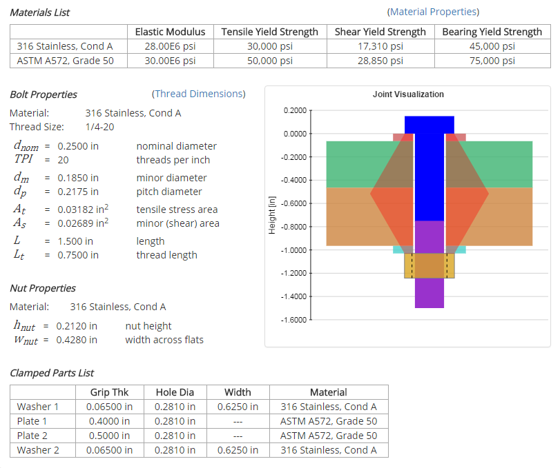
Joint Details
There are 2 main portions of the input form. The first portion relates to the bolt size and the overall joint details such as applied forces and joint type. In this case, a tensile force of 400 lbf and a shear force of 0 lbf are applied to the joint. The bolt chosen for the joint has a 1/4"-20 thread size and a material of 316 Stainless Steel. A nut will be used as the threaded member in the joint, and the bolt will be preloaded to 67% of the yield strength.
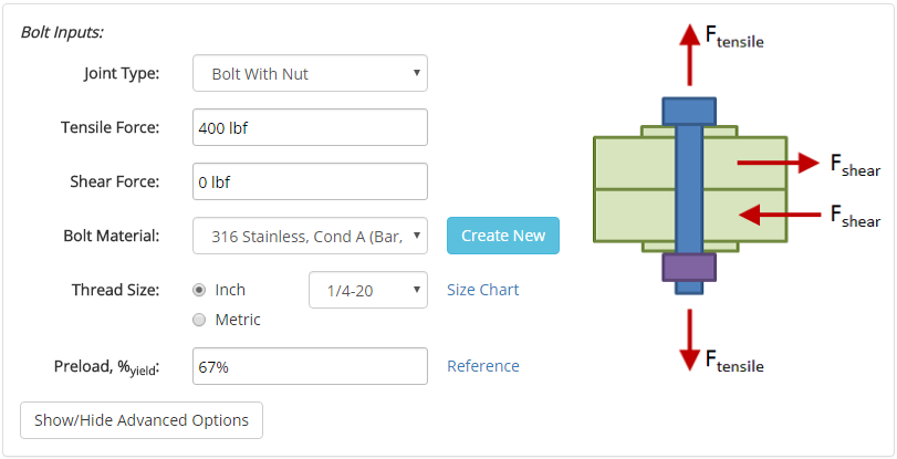
Materials are specified in a separate section of this site, and once materials are specified they will show up in the drop-down menu on the input form.
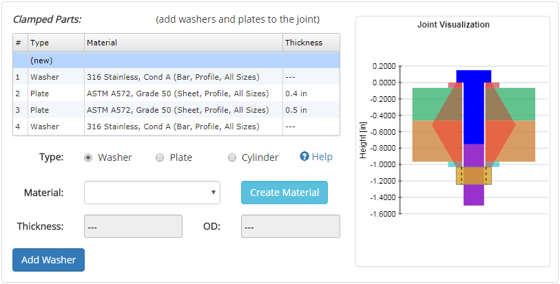
Clamped Parts
The second portion of the input form, shown below, relates to the geometry and materials of the clamped parts. These inputs are primarily used to calculate the grip stiffness which, in conjunction with the bolt stiffness, determines the portion of the applied load taken by the bolt. These inputs are also used to determine the clamped part stresses. In this case, two stainless steel washers are used in the joint (one under the bolt head and one under the nut), and two ASTM A572 steel plates are clamped together in the grip.
There are three different types of clamped parts that can be selected:
| • | Washers: | These are standard plain washers. The dimensions of the washers are determined based on the size of the bolt. |
| • | Plates: | Plates have a specified thickness and infinite width (so as not to restrict the frustum). The hole diameter is based on a normal fit clearance hole as specified here. If the plate is a tapped part, then the hole will be threaded with the same thread as the screw. |
| • | Cylinders: | Cylinders are the same as plates with the exception that an outer diameter is specified. The implication of this is that the frustum may be truncated if the outer diameter is narrow enough. Truncating the frustum will have the effect of reducing the stiffness of the grip and therefore increasing the load taken by the bolt. |
Once all of the inputs are entered, hitting the 'Submit' button will solve the analysis, and the results will be displayed.
Results
After the analysis is solved, results are displayed in multiple tabs. Each results tab is discussed in the following sections.
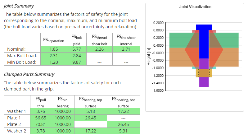
Results Summary
A summary of the results is provided to give a high-level overview of the factors of safety.
Joint Properties
After the analysis is solved, joint properties relevant to the analysis are displayed. These properties include material properties, geometries, and installation details.
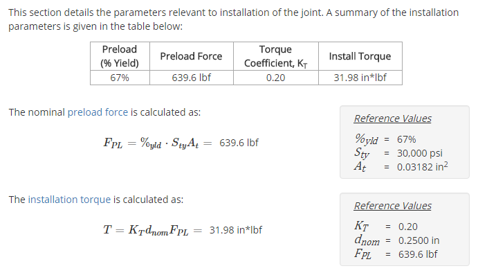
Joint Installation
A section is provided that details the parameters relevant to installation of the joint. The installation torque necessary to achieve the desired nominal preload force is calculated and displayed.
Bolt Forces & Stresses
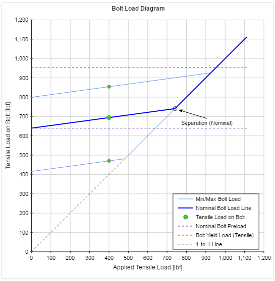
A section of the results is dedicated to the analysis of the forces and stresses on the bolt. The full section is long, but the highlights are provided here.
Of particular interest is the Bolt Load Diagram which shows the tensile force on the bolt as a function of applied tensile force and indicates whether the joint has separated and whether the bolt has failed. If any of the points on the diagram are shown in red then a failure has occurred.
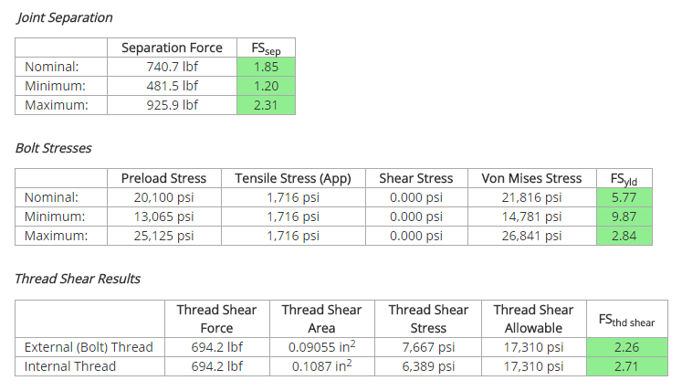
Also reported are the results for joint separation, the bolt stresses, and the thread shear for both internal and external thread.
Any Factor or Safety (FS) greater than 1 is highlighted in green, indicating a passing result. However, a margin should be employed to ensure adequate safety. It is up to the discretion of the engineer to determine the appropriate factor of safety to use in design.
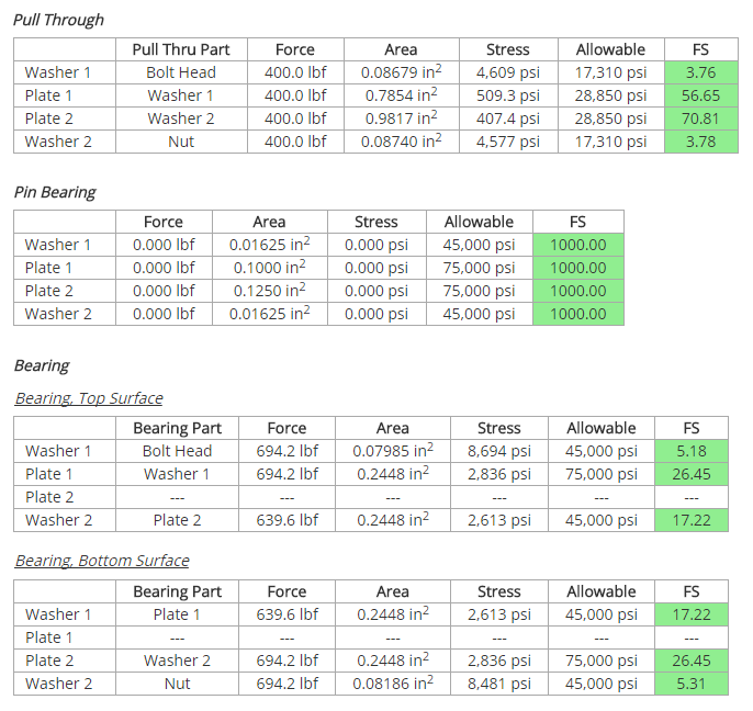
Clamped Part Stresses
The clamped part stresses are shown below. These results include pull through, bearing on the part surfaces, and pin bearing. The full section on clamped part stresses is long, but an example of the summary tables is provided here.
Any Factor or Safety (FS) greater than 1 is highlighted in green, indicating a passing result. However, a margin should be employed to ensure adequate safety. It is up to the discretion of the engineer to determine the appropriate factor of safety to use in design.