Fracture Mechanics
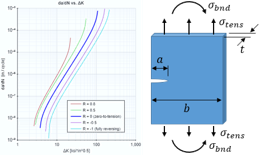
The Fracture Mechanics calculator allows for fracture analysis of a cracked part. The methods used include Linear Elastic Fracture Mechanics (LEFM), the Failure Assessment Diagram (FAD), and residual strength analysis. See the instructions within the documentation for more details on performing this analysis. See the reference section for details on the methodology and the equations used.
Inputs
Input the details for the fracture analysis and hit 'Submit' to calculate results:
Material Inputs
Advanced Options
This section gives advanced options which can be modified if desired. Otherwise, reasonable default options will be selected for you.
Applied Stresses
Display Units
Display results in:
Results
The results of the fracture analysis are detailed below. Refer to the fracture mechanics reference section for details on how these results were derived.
Results Summary
Summary tables of results are shown below. These tables give the factors of safety for the for the various analytical methods employed. Any factors of safety of at least 1 are shown in green, and below 1 are shown in red. It is the responsibility of the engineer to determine the appropriate factor of safety to use in design.
Linear Elastic Fracture Mechanics (LEFM)
The Factors of Safety (FS) for Linear Elastic Fracture Mechanics (LEFM) are given in the table below:
| FS at a-tip | FSLEFM.a | |
| FS at c-tip | FSLEFM.c |
LEFM does apply, so the factors of safety reported above may be used.
LEFM does not apply, so the factors of safety reported above should not be used. Use the factors of safety for FAD and residual strength instead.
Failure Assessment Diagram (FAD)
The Factor of Safety (FS) for the Failure Assessment Diagram (FAD) is given in the table below:
| FS for FAD | FSFAD |
Residual Strength
The Factors of Safety (FS) for Residual Strength are given in the table below:
| FS on critical stress | FSRSC.a | |
| FS on critical crack length | FSRSC.σ |
See full result details on the other tabs (above).
Properties & Inputs
This section details the crack geometry, material properties, and applied stresses.
Applied Stress
Material Properties
| Material: |
| Sty | = | yield strength | |
| Stu | = | ultimate strength | |
| E | = | elastic modulus | |
| eL | = | percent elongation | |
| K1C | = | plane-strain fracture toughness |
Flaw Tolerance Curve
Cannot calculate Flaw Tolerance Curve. Must specify a Percent Elongation value for material.
NAVSEA's Fracture Toughness Review Process (FTRP) defines a minimum material that is deemed to be fracture safe. The FTRP also defines a means of calculating a flaw tolerance curve for a material, which is an indication of the material's resistance to fracture. For a material to be considered fracture resistant, it must have a flaw tolerance curve above that of the minimum material curve.
Linear Elastic Fracture Mechanics (LEFM)
The Factors of Safety (FS) for Linear Elastic Fracture Mechanics (LEFM) are given below. Full detailed calculations are provided in the following sections.
| FS at a-tip | FSLEFM.a | |
| FS at c-tip | FSLEFM.c |
LEFM does apply, so the factors of safety reported above may be used.
LEFM does not apply, so the factors of safety reported above should not be used. Use the factors of safety for FAD and residual strength instead.
Overview
The stress intensity factor, K, is calculated and compared to the critical stress intensity (i.e. the fracture toughness), Kcrit. The stress intensity is calculated as:
where σ is the applied stress, a is the crack length, and Y is a dimensionless geometry factor that is dependent on the crack and part geometry.
Fracture Toughness vs. Thickness
The fracture toughness is dependent on part thickness. As the thickness increases the fracture toughness decreases until the plane-strain fracture toughness, K1C.
The fracture toughness (i.e. critical stress intensity) values for the plane-strain condition and for the current part thickness are provided in the table below:
| Plane-Strain Fracture Toughness | K1C = |
| Fracture Toughness at Part Thickness | Kc = |
For this analysis, we have elected to use the :
| Kcrit = | fracture toughness considered in this analysis |
Geometry Factor
The plot below shows the dimensionless geometry factors as a function of crack length.
It is important to note that in the plot, the proportions of the crack dimensions a and c are held constant as the crack is grown. This is a simplified approximation. If crack growth due to cyclic loading is a concern, then a fatigue crack growth analysis should be performed.
The table below provides the geometry factors for tension in bending at the a-tip and the c-tip:
| a-tip | c-tip | Description | |
|---|---|---|---|
| Yt | geometry factor for tension at a-tip and c-tip | ||
| Yb | geometry factor for bending at a-tip and c-tip |
Stress Intensity
The stress intensity factors at the a-tip and the c-tip are:
| At a-tip: |
|
|
| At c-tip: |
|
Reference Values
| a | = | |
| σt | = | |
| σb | = |
The Factors of Safety (FS) on LEFM at the a-tip and the c-tip are:
| At a-tip: |
|
|
|
| At c-tip: |
|
|
Reference Values
| Kcrit | = | |
| Kapp.a | = | |
| Kapp.c | = |
Plastic Zone Size
Plane-Stress vs. Plane-Strain
The size of the plastic zone is dependent on whether the part is considered to be in a plane-stress or a plane-strain condition. The minimum thickness for the part to be in plane-strain is:
|
|
Reference Values
| Kapp.max | = | |
| Sty | = |
The actual part thickness of is than the minimum plane-strain thickness, so the part is considered to be in the condition.
Plastic Zone Size
The equation for the plastic zone size is dependent on whether the part is considered to be in plane-stress or plane-strain:
| Variable | Equation |
|---|---|
| Plastic zone size for plane-stress: |
|
| Plastic zone size for plane-strain: |
|
This part is in plane-strain, so the plastic zone size is:
|
|
This part is in plane-stress, so the plastic zone size is:
|
|
Applicability of LEFM
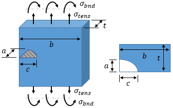
For LEFM to be applicable, the plastic zone size must be small relative to the part and crack geometry. The plastic zone is situated just ahead of the crack tip. In general, the tip of the crack must be a distance of at least dLEFM from any part boundary, where dLEFM is defined below:
|
|
Reference Values
| Kapp.max | = | |
| Sty | = |
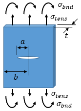
The crack type is a through crack in the center of a plate. In this case, the minimum distance from the crack tip to the part boundary is:
|
dbound = b − a =
|
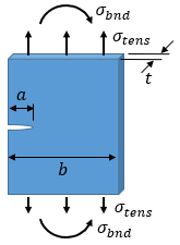
The crack type is a through crack at the edge of a plate. In this case, the minimum distance from the crack tip to the part boundary is:
|
dbound = min[ a, (b − a) ] =
|
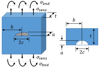
The crack type is an elliptical surface crack in a plate. In this case, the minimum distance from the crack tip to the part boundary is:
|
dbound = min[ a, (t − a), (b − c) ] =
|
The crack type is a corner surface crack in a plate. In this case, the minimum distance from the crack tip to the part boundary is:
|
dbound = min[ a, c, (t − a), (b − c) ] =
|
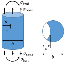
The crack type is a thumbnail crack in a solid cylinder. In this case, the minimum distance from the crack tip to the part boundary is:
|
dbound = min[ a, (b − a) ] =
|
The value of dbound is than the distance dLEFM, so .
Failure Assessment Diagram (FAD)
Cannot calculate FAD results. Must specify a Percent Elongation value for material.
The Factor of Safety (FS) for the Failure Assessment Diagram (FAD) is given below. Full detailed calculations are provided in the following section.
| FS for FAD | FSFAD |
The Failure Assessment Diagram (FAD) accounts for both elastic and plastic material behavior. The material behavior is defined by the stress ratio, Sr, and the stress intensity ratio, Kr.
The ratios for the current case are:
| Stress Ratio: |
|
|
| Stress Intensity Ratio: |
|
Reference Values
| σcmb | = | |
| Kapp | = | |
| Sty | = | |
| K1C | = |
The critical stress ratio and stress intensity ratio are the ratios at which failure occurs, and occur when the load line in the FAD diagram intersects the failure locus:
| Critical Stress Ratio: | Sr.crit = | |
| Critical Stress Intensity Ratio: | Kr.crit = |
The critical stress, σcrit, and the critical stress intensity, Kcrit, are the σ and K values at which failure occurs:
| Critical Stress: | σcrit = Sr.crit·Sty = | |
| Critical Stress Intensity: | Kcrit = Kr.crit·K1C = |
Reference Values
| Sr.crit | = | |
| Kr.crit | = | |
| Sty | = | |
| K1C | = |
The Factor of Safety (FS) is based on length of the load line to the current point compared to the length of load line to the intersection (critical) point:
| FSFAD = |
|
Residual Strength
The Factors of Safety (FS) for Residual Strength are given below. Full detailed calculations are provided in the following section.
| FS on critical stress | FSRSC.a | |
| FS on critical crack length | FSRSC.σ |
Residual Strength Curve
The Residual Strength Curve shows the strength of the part as a function of crack size. If no crack is present, the part strength is equal to the yield strength. However, as the crack grows, the strength is reduced.
The Residual Strength Curve for the current case is shown below. The intersection of the current case with the curve in the vertical direction gives the critical stress for the current crack length. The intersection in the horizontal direction gives the critical crack length for the current applied stress level.
The critical values for the current case are:
| Critical Stress: | σcrit = | |
| Critical Crack Length: | acrit = |
The Factors of Safety (FS) for the current case are:
| FS on critical stress: |
|
|
|
| FS on critical crack length: |
|
|
Reference Values
| σcmb | = | |
| a | = | |
| σcrit | = | |
| acrit | = |
Download Report
Save a formatted Word document to your computer detailing the inputs and results of the analysis.
Download Inputs File
Save all input data to a file. You can later upload this file to pick back up where you left off.
Need More Functionality?
Sign up for an account to receive full access to all calculators and other content. The subscription types are described below, along with the benefits of each.
- Price
- Access to Calculators
- Login
- Create Materials
- Create Cross Sections
- Save Files
- Reporting
- Free
-
LimitedLimited Access to Calculators
-
NoneNo Login
-
Pre-defined Materials
-
Pre-defined Cross Sections
-
No Saved Files
-
No Reporting
- Learn More »
-
USD $9.99 /month USD $99.99 /year -
FullFull Access to Calculators
-
IndividualIndividual Login
-
Create Materials
-
Create Cross Sections
-
Unlimited Saved Files
-
Unlimited Reporting
- Learn More »
- Sign Up Now
-
USD $29.99 /month USD $299.99 /year -
FullFull Access to Calculators
-
Floating LicensesFloating Licenses
-
Create Materials
-
Create Cross Sections
-
Unlimited Saved Files
-
Unlimited Reporting
- Learn More »
- Sign Up Now
-
Bulk pricing (≥20 educational licenses)
-
FullFull Access to Calculators
-
Floating LicensesFloating Licenses
-
Create Materials
-
Create Cross Sections
-
Unlimited Saved Files
-
Unlimited Reporting
- Learn More »
- Sign Up Now
Solving, please wait...

Looking for Other Calculators?
Here are just a few of the calculators that we have to offer:
Feedback
Do you have any comments or suggestions? We would love to hear them!
