Fracture Mechanics Instructions
This page provides instructions on the use of the Fracture Mechanics calculator. This calculator allows for fracture analysis of a cracked part.
Reference and Validation
Reference: A general description of the theory and the methodology used can be found here.
Validation: This calculator has been validated against known solutions to numerous example problems. Documentation of the validation can be found here.
Inputs
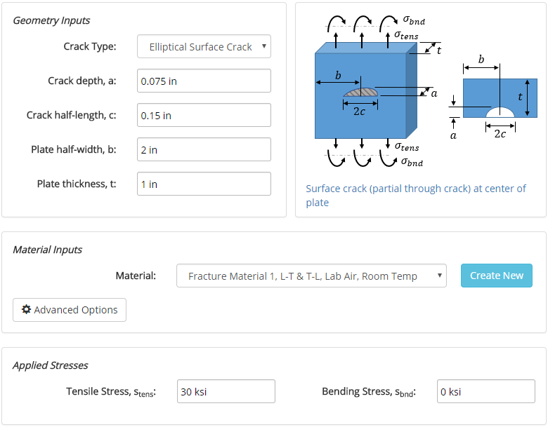
In this section, all of the relevant details pertaining to the analysis are entered. These inputs relate to the crack geometry, plate geometry, material, and applied stresses.
The input form is shown below. In this case, an elliptical surface crack is specified at the center of a plate. The material assigned to the plate is an example material, "Fracture Material 1," and a tensile stress of 30 ksi is applied at the ends of the plate. No bending stress is applied.
Fracture materials can be created within the fracture materials database. Once materials are created, they will show up in the drop-down menus on the input form.
Results
After the analysis is solved, results are displayed in multiple tabs. Each results tab is discussed in the following sections.
Results Summary
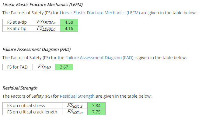
A summary of the results is provided to give a high-level overview of the factors of safety for the various analytical methods employed. Any factors of safety of at least 1 are shown in green, and below 1 are shown in red. It is the responsibility of the engineer to determine the appropriate factor of safety to use in design.
Properties
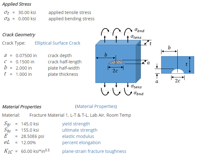
After the analysis is solved, properties relevant to the analysis are displayed. These properties include material properties, crack geometry, and applied stresses. The way in which these properties are used in the analysis is described in more detail in the Reference section.
Linear Elastic Fracture Mechanics (LEFM)
There are 3 analytical methods employed in this calculator, one of which is Linear Elastic Fracture Mechanics (LEFM). The results section for the LEFM method is long, but the highlights are provided here.
The fracture toughness of a material is dependent on part thickness. This calculator provides a curve for the fracture toughness as a function of part thickness for the material considered in the analysis:

The geometry factor, Y, is dependent on the geometry of the part and the crack. This calculator provides a curve for the geometry factor as a function of crack length for the specific crack geometry considered in the analysis:

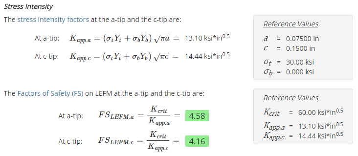
The values of the geometry factor and the applied stress can be used to calculate the stress intensity factors. The stress intensity factors can then be compared to the critical stress intensity (fracture toughness) of the material to determine the factor of safety:
Failure Assessment Diagram (FAD)
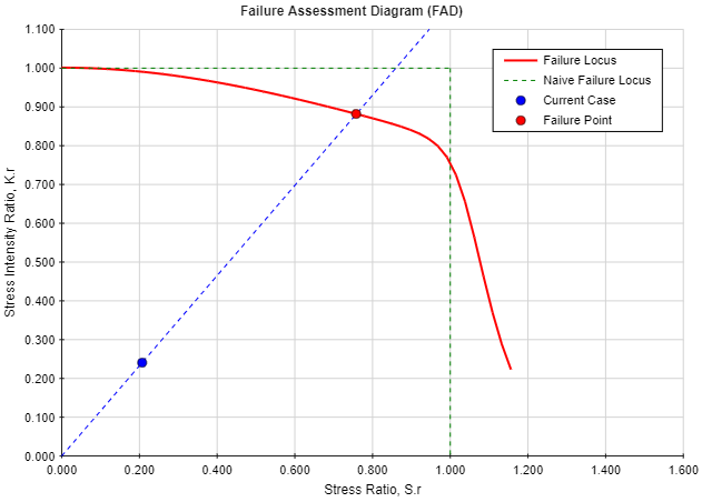
The Failure Assessment Diagram (FAD) is the second of the 3 analytical methods employed in this calculator. The FAD diagram accounts for both elastic and plastic material behavior:
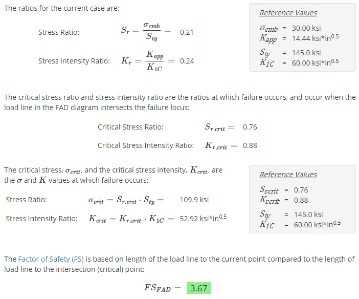
The material behavior is defined by the stress ratio, Sr, and the stress intensity ratio, Kr. The ratios for the current case are calculated, along with the Factor of Safety:
Residual Strength
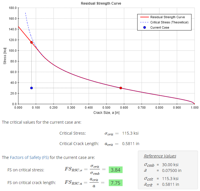
The Residual Strength Curve is the final of the 3 analytical methods employed in this calculator. The Residual Strength Curve shows the strength of the part as a function of crack size. If no crack is present, the part strength is equal to the yield strength. However, as the crack grows, the strength is reduced.
The Residual Strength Curve for the current case is shown below, along with the Factor of Safety: