2D FEA Validation
This section details the validation for the 2D FEA calculator. Several examples are worked through to determine expected results such as deflections, forces, and stresses. These expected results are then compared to the actual output of the 2D FEA.
Frame
In this validation, a simple frame structure is analyzed. The frame is made up of 3 beams, each of which has a material of Aluminum 6061-T6 and a 1 inch diameter circular cross-section.
The legs of the frame are each 10 inches long, and the cross bar at the top of the frame is 20 inches long. A force of 1000 lbf is applied at the center of the cross bar.
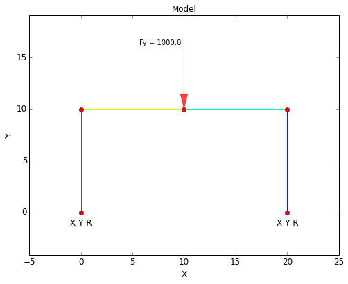
The inputs for this example are:
The Free Body Diagram (FBD) for the validation case is shown below. Note that the base of both legs are fixed in all degrees of freedom, and so this problem is indeterminate (6 reactions but only 3 equations). However, it can be seen that the reactions in Y balance with the applied force.
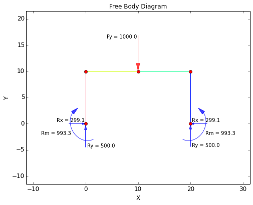
The connection between the cross bar and the legs of the frame is a stiff connection (i.e. 'welded'). Since the legs of the frame provide some compliance, the deflection of the cross bar can be expected to fall between the following two cases:
- Simply supported beam with center load
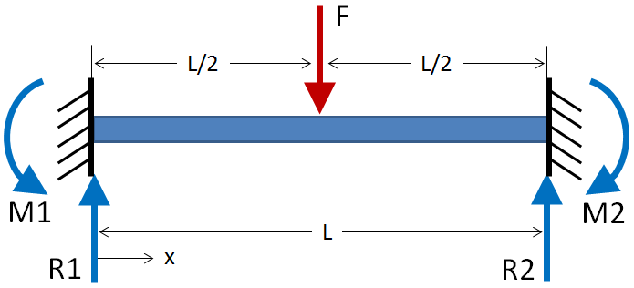
- Fixed-fixed beam with center load
Given that the cross bar has a length of 20 inches, the expected results when considering the bar to be either a simply supported beam or a fixed-fixed beam are:
| Simply Supported | Fixed-Fixed | |
|---|---|---|
| FBD: | 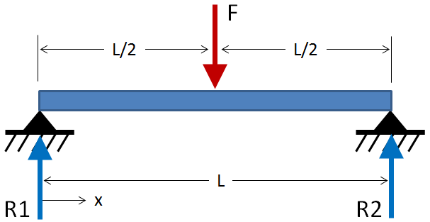 |
 |
| Max Deflection: | $$ \delta_{max} = {F L^3 \over 48EI} = 0.33953 \text { in} $$ | $$ \delta_{max} = {F L^3 \over 192EI} = 0.08488 \text { in} $$ |
| Max Moment: | $$ M_{max} = {FL \over 4} = 5000 \text { in-lbf} $$ | $$ M_{max} = {FL \over 8} = 2500 \text { in-lbf} $$ |
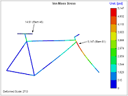
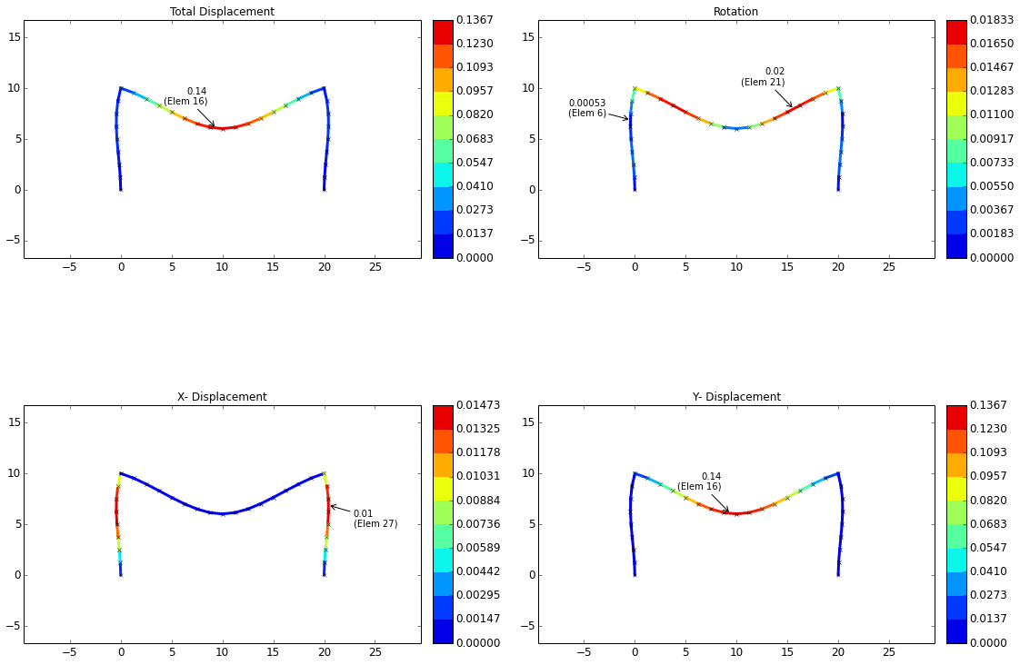
The displacements from the validation case are shown below. From these plots it can be seen that the maximum deflection of the cross bar is 0.1367 inches. This deflection falls in between the simply supported and the fixed-fixed cases above, although it is somewhat closer to the fixed-fixed case.
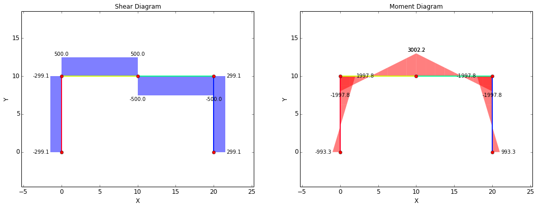
The shear-moment diagram for the beam is shown below. This diagram is what would be expected for the current case. A constant shear force of +500 lbf exists from the left end of the beam until the location of the applied force at the center of the cross bar, after which the shear force is -500 lbf until the right end of the beam. The moment is maximum at the center of the cross-bar, as expected, with a value of 3002.2 in-lbf. This maximum value is between the simply supported and the fixed-fixed cases, although it is somewhat closer to the fixed-fixed case.
