Lug Analysis Validation
In Section 9.6 of the Air Force Stress Analysis Manual, an example is provided for an axially loaded lug. The male lug strength, female lug strength, and double shear joint strength are calculated. This validation case follows the Air Force example to ensure consistent results between the Air Force Manual and MechaniCalc's Lug Analysis calculator.
Female Lugs and Bushings
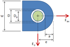
The inputs for the female lug, per the input table, are specified below:
Geometry:
| D | = | 1 in | hole diameter |
| e | = | 1.25 in | edge distance (hole center to edge of lug) |
| a | = | 0.75 in | distance (edge of hole to edge of lug) |
| w | = | 2.5 in | width |
| t1 | = | 0.5 in | thickness |
Material Properties: 2024-T351 Plate
| Sty | = | 40,000 psi | tensile yield strength |
| Stu | = | 64,000 psi | tensile ultimate strength |
| E | = | 10.5 x 10⁶ psi | elastic modulus |
| εu | = | 0.12 | ultimate strain |
Comparison Summary
A summary of the female lug results calculated in the Air Force Manual versus those calculated in MechaniCalc's Lug Analysis calculator is provided below. It can be seen that the results are essentially equivalent. Any differences are due to slight variations in determining the \(K\) coefficients from the charts, or are due to rounding errors.
| Air Force Manual | MechaniCalc Lug Calculator | |
|---|---|---|
| Lug Bearing Strength | 28,600 lbf | 28,440 lbf |
| Lug Net-Section Tension Strength | 28,949 lbf | 28,960 lbf |
| Bushing Bearing Strength | 29,300 lbf | 29,340 lbf |
| Combined Lug-Bushing Design Strength | 28,600 lbf | 28,440 lbf |
Lug Bearing Strength
The female lug bearing strength as calculated in the Air Force Manual is:

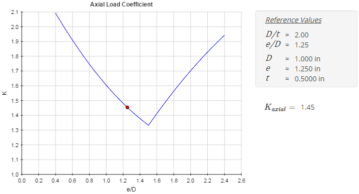
The results from the Lug Analysis calculator are shown below. The predicted bearing strength is just slightly below that calculated in the Air Force Manual (28,440 lbf vs. 28,600 lbf) due to a slightly lower \( K_{axial} \) value read off of the figure (1.45 vs. 1.46). The strength values are within 0.56%.

Lug Net-Section Tension Strength
The female lug net-section tension strength as calculated in the Air Force Manual is:

It should be noted that the net tension strength calculated in the Air Force Manual above is multiplied by 2 since there are 2 female lugs in the joint. However, all of the other female lug strength values in the example (e.g. bearing strength, design strength, etc.) are calculated for a single lug. If the strength above were divided by 2 to account for just a single lug, the result would be:
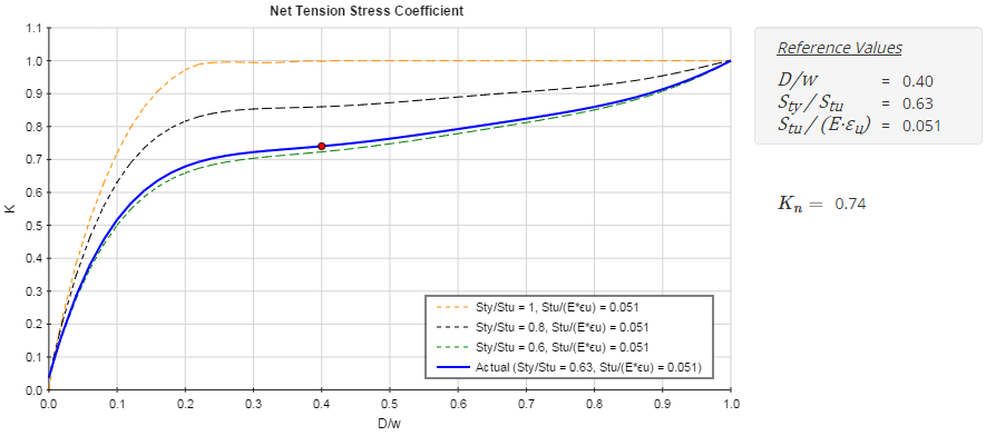
$$ P_{nu.L.single} = { P_{nu.L} \over 2 } = { 57,898 \text{ lbf} \over 2 } = 28,949 \text{ lbf} $$The results from the Lug Analysis calculator are shown below. The predicted bearing strength is equivalent (within 0.04%) to the value calculated in the Air Force Manual. Any differences can be attributed to slight differences in determining the net tension stress coefficient (there are additional decimal places that are not shown in the displayed value).

Lug Design Strength
The female lug design strength as calculated in the Air Force Manual is:

MechaniCalc's Lug Analysis calculator does not determine a design strength until the bushing bearing strength has also been calculated (in the next step).
Bushing Bearing Strength
The female bushing bearing strength as calculated in the Air Force Manual is:

The results from the Lug Analysis calculator are shown below. The predicted bearing strength is equivalent to the value calculated in the Air Force Manual (with the only differences being attributable to rounding on the part of the Air Force Manual):

Combined Lug-Bushing Design Strength
The combined female lug-bushing design strength as calculated in the Air Force Manual is:

The results from the Lug Analysis calculator are shown below. The predicted strength is equivalent to the value calculated in the Air Force Manual:

